PAGE 50
7.3B 12 & 24 INCH BRAKE OPERATION
NEVER PUT YOUR HANDS INTO OR AROUND A BRAKE WHILE IT IS IN OPERATION.
Hold short pieces with tongs or a similar device.
In using the brake, it is necessary to load the brake centrally. (Visual centering is sufficient.)
If the work is performed off-center, the guide pins could be damaged.
The brake lift is provided by the springs.
If sticking occurs at the bottom of the stroke and the upper die does not return, usually a slight tap on the
upper die is sufficient to free the guides.
DO NOT ATTEMPT TO FREE THE BRAKE BY HAND.
Sticking can be caused by lack of lubrication, complexity of the part being bent or bent guide pins.
Keep the guides well lubricated and replace them if they are damaged.
It is common practice to have the bottom die opening 8 times the thickness of the material being bent.
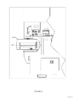
For tonnage requirements, SEE FIGURE 23 ON THE FOLLOWING PAGE.
If parts require bends of less than 90 degrees, adjust the stroke until the desired bend is obtained.
A great variety of standard brake dies can be used with this unit.
Dies are available from Scotchman Industries or your local dealer.
All brakes are shipped with 2 inch (50mm) vee opening dies, unless otherwise specified.
The brakes on this machine have 85 tons of force available.
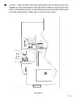
CAUTION: TO PREVENT POSSIBLE INJURY TO PERSONNEL AND DAMAGE TO THE
TOOL, THIS TOOL MUST BE REMOVED WHEN IT IS NOT IN USE.
Summary of Contents for FI-8510-20M
Page 10: ...PAGE 9 FIGURE 1...
Page 12: ...PAGE 11 FIGURE 2...
Page 24: ...PAGE 21 FIGURE 6...
Page 26: ...PAGE 23 FIGURE 7...
Page 38: ...PAGE 35 FIGURE 15...
Page 40: ...PAGE 37 FIGURE 16...
Page 42: ...PAGE 39 FIGURE 17...
Page 48: ...PAGE 45 FIGURE 20...
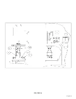
Page 50: ...PAGE 47 FIGURE 21...
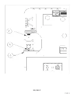
Page 52: ...PAGE 49 FIGURE 22...
Page 56: ...PAGE 53 FIGURE 24...
Page 58: ...PAGE 55 FIGURE 25...
Page 62: ...PAGE 59 FIGURE 26...
Page 64: ...PAGE 61 FIGURE 27...
Page 68: ...PAGE 65 FIGURE 29...
Page 74: ...PAGE 71 FIGURE 30...
Page 76: ...PAGE 73 FIGURE 31...
Page 80: ...PAGE 77 FIGURE 33...
Page 82: ...PAGE 79 FIGURE 34...
Page 84: ...PAGE 81 FIGURE 35...
Page 88: ...PAGE 85 FIGURE 37...
Page 90: ...PAGE 87 FIGURE 38...
Page 92: ...PAGE 89 FIGURE 39...
Page 94: ...PAGE 91 FIGURE 40...
Page 96: ...PAGE 93 FIGURE 41...
Page 100: ...PAGE 97 FIGURE 43 SERIAL S 4481 UP...

