PAGE 34
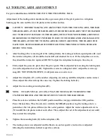
6.3 TOOLING ARM ADJUSTMENT
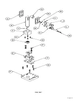
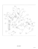
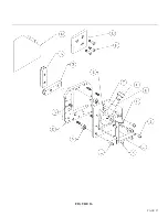
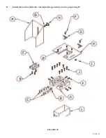
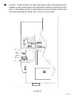
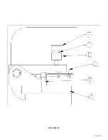
For parts identification, SEE FIGURE 15 ON THE FOLLOWING PAGE.
Adjustment of the tooling arm is maintained by a pressure plate at the pivot point, two rub plates
backing up the arm and the two rub plates at the notcher station.
CAUTION: BEFORE MAKING ANY ADJUSTMENTS ON THE TOOLING ARM, THE BAR
SHEAR BLADES, ANGLE SHEAR BLADES AND ROD SHEAR BLADES MUST BE BACKED
OFF TO PREVENT DAMAGE TO THE BLADES. THE LOWER NOTCHER BLADES MUST
BE REMOVED TO PREVENT POSSIBLE INJURY TO THE OPERATOR AND DAMAGE TO
THE BLADES. AFTER THE TOOLING ARM HAS BEEN ADJUSTED, THE BLADES FOR
EACH TOOL SHOULD BE READJUSTED FOLLOWING THE INSTRUCTIONS FOR EACH
RESPECTIVE TOOL.
1.
After backing off or removing all of the tooling blades, the tooling arm back-up rub plates (H) and
the notcher rub plates (P) should be backed off and checked for wear. If the rub plates are worn,
they should be rotated or replaced. DO NOT adjust the rub plates back up to the arm yet.
2.
First, adjust the pressure plate (I) at the pivot point. This is adjusted by loosening the locking nuts
(S) on the adjustment screws (R). Tighten the screws in a diagonal order. Adjust the screws up
snug. DO NOT OVER-TIGHTEN; it will just cause excessive wear.
3.
Adjust the rub plates (P) on the notcher, adjusting one side up until the rub plates make contact.
Then, adjust the other side up the same way. Tighten the locking bolts (O).
4.
Adjust the two tooling arm rub plates (H).
NOTE: TO GAIN VISUAL ACCESS, IT MAY BE NECESSARY TO REMOVE THE
CYLINDER SHROUD AND THE DROP-OFF COVER ON THE BAR SHEAR.
5.
Place the selector switch in the START position and the run/jog switch in the JOG position.
Power the machine. Place the selector switch in the SHEAR position. Jog the tooling arm to a
point where the rub plates will meet in the center position. Adjust the center adjustment screws
(N) in until the rub plates contact each other. Then, adjust the rest of the adjustment screws until
they contact the rub plate.
6.
Tighten the mounting bolts (O) in the rub plates (H).
7.
The tooling arm is now adjusted and the blades on each respective tool can be readjusted
following the instructions in their respective sections.
Summary of Contents for FI-8510-20M
Page 10: ...PAGE 9 FIGURE 1...
Page 12: ...PAGE 11 FIGURE 2...
Page 24: ...PAGE 21 FIGURE 6...
Page 26: ...PAGE 23 FIGURE 7...
Page 38: ...PAGE 35 FIGURE 15...
Page 40: ...PAGE 37 FIGURE 16...
Page 42: ...PAGE 39 FIGURE 17...
Page 48: ...PAGE 45 FIGURE 20...
Page 50: ...PAGE 47 FIGURE 21...
Page 52: ...PAGE 49 FIGURE 22...
Page 56: ...PAGE 53 FIGURE 24...
Page 58: ...PAGE 55 FIGURE 25...
Page 62: ...PAGE 59 FIGURE 26...
Page 64: ...PAGE 61 FIGURE 27...
Page 68: ...PAGE 65 FIGURE 29...
Page 74: ...PAGE 71 FIGURE 30...
Page 76: ...PAGE 73 FIGURE 31...
Page 80: ...PAGE 77 FIGURE 33...
Page 82: ...PAGE 79 FIGURE 34...
Page 84: ...PAGE 81 FIGURE 35...
Page 88: ...PAGE 85 FIGURE 37...
Page 90: ...PAGE 87 FIGURE 38...
Page 92: ...PAGE 89 FIGURE 39...
Page 94: ...PAGE 91 FIGURE 40...
Page 96: ...PAGE 93 FIGURE 41...
Page 100: ...PAGE 97 FIGURE 43 SERIAL S 4481 UP...

