PAGE 67
5.
Check the fuses in the control box. There are two fuses on the primary side and one on the
secondary side. Remove the fuses and check them with an Ohm meter.
6.
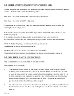
Check the limit switches. (For procedures, REFER TO SECTION 8.2 ON THE FOLLOWING
PAGE.)
7.
No power from the transformer: Check the voltage across the transformer’s secondary
terminals. It should read 110 to 120 volts.
8.
The solenoid on the control valve is not functioning. REFER TO SECTION 8.3.
9.
The foot pedal switch is not functioning properly. A voltage test may be run on the terminal strip
in the control box to determine if the foot switch is working properly.
WARNING: THERE IS LINE VOLTAGE PRESENT IN THE CONTROL BOX WHEN THE
MACHINE IS POWERED. THESE TESTS SHOULD BE PERFORMED BY A QUALIFIED
ELECTRICIAN.
TO TEST THE FOOT SWITCH:
Power the machine and place the selector switch in either the PUNCH or the SHEAR position.
Test the voltage between terminal #’s 5, 10 and ground.
With the pedal up, the voltage should read 110 to 120 volts between 5 and ground.
There should be no voltage reading between 10 and ground.
With the pedal depressed, the voltage should read 110 to 120 volts between 10 and ground.
There should be no voltage reading between 5 and ground.
IF THESE READINGS ARE NOT CORRECT, continue on with the following steps.
A.
Turn off the machine’s power and remove the cover on the foot pedal. Check for loose
connections.
B.
Make sure that the switches are adjusted properly. (You should hear two distinct "clicks"
approximately 1/2 inch (12mm) apart when depressing the pedal.) There is a set screw adjustment
on the pedal shaft to adjust the switches.
C.
Check the switches with an Ohm meter.
10.
Damage to the foot pedal cord: Check the continuity of the wires in the cord with an Ohm meter.
Make sure that the power to the machine is off and locked out. The wires must be disconnected
from the pedal and the terminal block.
11.
The pump to motor coupler is damaged. Loosen the set screws in the pump and motor flanges and
slide them apart. Inspect the coupler. If it is damaged, replace it.
Summary of Contents for FI-8510-20M
Page 10: ...PAGE 9 FIGURE 1...
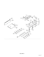
Page 12: ...PAGE 11 FIGURE 2...
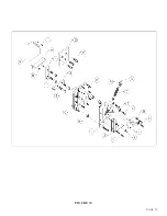
Page 24: ...PAGE 21 FIGURE 6...
Page 26: ...PAGE 23 FIGURE 7...
Page 38: ...PAGE 35 FIGURE 15...
Page 40: ...PAGE 37 FIGURE 16...
Page 42: ...PAGE 39 FIGURE 17...
Page 48: ...PAGE 45 FIGURE 20...
Page 50: ...PAGE 47 FIGURE 21...
Page 52: ...PAGE 49 FIGURE 22...
Page 56: ...PAGE 53 FIGURE 24...
Page 58: ...PAGE 55 FIGURE 25...
Page 62: ...PAGE 59 FIGURE 26...
Page 64: ...PAGE 61 FIGURE 27...
Page 68: ...PAGE 65 FIGURE 29...
Page 74: ...PAGE 71 FIGURE 30...
Page 76: ...PAGE 73 FIGURE 31...
Page 80: ...PAGE 77 FIGURE 33...
Page 82: ...PAGE 79 FIGURE 34...
Page 84: ...PAGE 81 FIGURE 35...
Page 88: ...PAGE 85 FIGURE 37...
Page 90: ...PAGE 87 FIGURE 38...
Page 92: ...PAGE 89 FIGURE 39...
Page 94: ...PAGE 91 FIGURE 40...
Page 96: ...PAGE 93 FIGURE 41...
Page 100: ...PAGE 97 FIGURE 43 SERIAL S 4481 UP...

