Page 40
This tool is operated with the selector switch in the PUNCH position.
6.6 RECTANGLE NOTCHER OPERATION
Notching applications up to 3 x 5 inch (76 x 127mm) rectangular and 3 x 3 inch (76 x 76mm) 90 degree
vee notch in 1/2 inch (12mm) material is the maximum capacity of this section of the machine.
TO OPERATE THE NOTCHER, USE THE FOLLOWING STEPS:
1.
Always maintain 1/4 of an inch (6.3mm) clearance between the material and the guard.
2.
Place the workpiece between the blades. Cycle the machine until the blades have sheared through
the material. Continue to hold your foot on the pedal while you remove the material toward you
on a horizontal plane.
3.
Once the material is away from the blades, remove your foot from the pedal. The machine will
return to a neutral position, ready for the next cut.
4.
DO NOT USE THE SAFETY GUARD AS A STRIPPER!
The safety guard will not support the load. Lubricate the blades every 10 to 15 cuts.
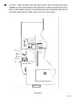
CAUTION: WHEN THE NOTCHER STATION IS NOT IN USE, BE SURE THAT THE
GUARD IS IN THE FULL DOWN POSITION, TO PREVENT ANYONE FROM
STORING TOOLS OR MATERIAL ON THE TABLE OR IN THE BLADE CAVITY.
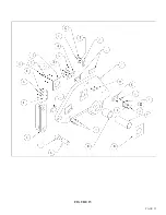
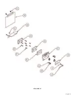
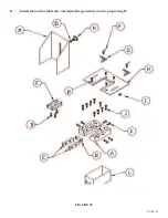
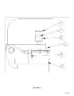
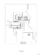
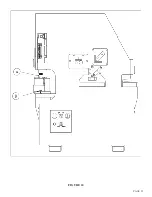
For parts identification, SEE FIGURE 18 ON THE FOLLOWING PAGE.
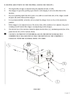
1.
Place the machine in the PUNCH position and allow the machine to retract to the end of the stroke.
TURN THE POWER TO THE MACHINE OFF!
2.
Raise the notcher guard (M) to its highest position.
3.
Remove the notcher table (H).
4.
Remove the bolts (J) holding the lower blade holder (A) and remove it.
5.
The lower blades (B &C) can now be replaced or rotated, to expose a new cutting edge.
6.
Remove the top blade (E). The top blade cannot be rotated and must be replaced, if damaged.
Before installing a new top blade, check the arm for possible wear. If there is no wear, install the
new blade on the arm.
7.
Place the selector switch in the START position and the run/jog switch in the JOG position.
Power the machine.
8.
Place the selector switch in the PUNCH position. Jog the arm down to a point where the top blade
is parallel with the bolster. TURN THE POWER OFF.
9.
Replace the lower blade holder (A) with the blades (B & C) installed. Start the mounting bolts (J).
DO NOT TIGHTEN.
10.
Manually align the lower blades to the upper blades with equal clearance all the way around. A
clearance of twenty five thousandths (.025) of an inch (.6mm) is recommended. The lower blades
may require shimming to achieve the proper clearance. Tighten the blade holder bolts to
approximately 85 foot pounds of torque. Recheck the alignment.
6.6A NOTCHER BLADE ADJUSTMENT OR REPLACEMENT
Summary of Contents for FI-8510-20M
Page 10: ...PAGE 9 FIGURE 1...
Page 12: ...PAGE 11 FIGURE 2...
Page 24: ...PAGE 21 FIGURE 6...
Page 26: ...PAGE 23 FIGURE 7...
Page 38: ...PAGE 35 FIGURE 15...
Page 40: ...PAGE 37 FIGURE 16...
Page 42: ...PAGE 39 FIGURE 17...
Page 48: ...PAGE 45 FIGURE 20...
Page 50: ...PAGE 47 FIGURE 21...
Page 52: ...PAGE 49 FIGURE 22...
Page 56: ...PAGE 53 FIGURE 24...
Page 58: ...PAGE 55 FIGURE 25...
Page 62: ...PAGE 59 FIGURE 26...
Page 64: ...PAGE 61 FIGURE 27...
Page 68: ...PAGE 65 FIGURE 29...
Page 74: ...PAGE 71 FIGURE 30...
Page 76: ...PAGE 73 FIGURE 31...
Page 80: ...PAGE 77 FIGURE 33...
Page 82: ...PAGE 79 FIGURE 34...
Page 84: ...PAGE 81 FIGURE 35...
Page 88: ...PAGE 85 FIGURE 37...
Page 90: ...PAGE 87 FIGURE 38...
Page 92: ...PAGE 89 FIGURE 39...
Page 94: ...PAGE 91 FIGURE 40...
Page 96: ...PAGE 93 FIGURE 41...
Page 100: ...PAGE 97 FIGURE 43 SERIAL S 4481 UP...

