Page 54
The channel shear is a component tool designed to shear 2 to 6 inch (51 to 152mm) standard channel. It is
mounted in the punch station and is operated with the selector switch in the PUNCH position.
7.5 CHANNEL SHEAR
►
NOTE: THE BOLSTER MUST BE REMOVED FIRST, TO ALLOWROOM FOR THIS TOOL.
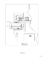
For clarity, the tool is shown with the guard removed. DO NOT operate the tool with the guard removed.
7.5A CHANNEL SHEAR INSTALLATION
1.
Place the selector switch in the PUNCH position and allow the ram to retract. Turn the power to
the machine off.
2.
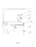
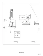
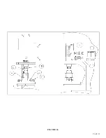
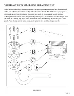
Before installing the tool on the machine, remove the top blade (A) and install the spring guide
rods (B) and springs. (REFER TO THE INSERT IN FIGURE 25.) Install the spring guide rods
with the head down in the tool.s side plate. Then, install the springs on the rods.
3.
Replace the top blade (A).
4.
There is an extra set of backup set screws for the stationary vertical blades. These longer screws
must be used when shearing smaller channel.
5.
Because of clearances, it is necessary to mount the finger clamps (C) to the punch bed and start
the bolts before installing the tool.
6.
After the finger clamps are in place, slide the tool onto the punch bed under the finger clamps.
7.
Align the tool so that the punch ram will come down directly over, and be evenly distributed on,
the pressure block of the tool. If the ram pressure is not evenly distributed on the pressure block,
the side load may cause damage to the tool.
8.
After a visual inspection has been made on the lineup, tighten the finger clamp bolts.
9.
Place the selector switch in the START position and the run/jog switch in the JOG position. Power
the machine and place the selector switch in the PUNCH position.
10.
Jog the punch ram down to within 1/8 of an inch (3mm) of the pressure block on the tool and set
the upper stroke control. Set the lower stroke control as low as possible, without bottoming out the
ram on any part of the tool.
11. Place the run/jog switch in the RUN position.
Summary of Contents for FI-8510-20M
Page 10: ...PAGE 9 FIGURE 1...
Page 12: ...PAGE 11 FIGURE 2...
Page 24: ...PAGE 21 FIGURE 6...
Page 26: ...PAGE 23 FIGURE 7...
Page 38: ...PAGE 35 FIGURE 15...
Page 40: ...PAGE 37 FIGURE 16...
Page 42: ...PAGE 39 FIGURE 17...
Page 48: ...PAGE 45 FIGURE 20...
Page 50: ...PAGE 47 FIGURE 21...
Page 52: ...PAGE 49 FIGURE 22...
Page 56: ...PAGE 53 FIGURE 24...
Page 58: ...PAGE 55 FIGURE 25...
Page 62: ...PAGE 59 FIGURE 26...
Page 64: ...PAGE 61 FIGURE 27...
Page 68: ...PAGE 65 FIGURE 29...
Page 74: ...PAGE 71 FIGURE 30...
Page 76: ...PAGE 73 FIGURE 31...
Page 80: ...PAGE 77 FIGURE 33...
Page 82: ...PAGE 79 FIGURE 34...
Page 84: ...PAGE 81 FIGURE 35...
Page 88: ...PAGE 85 FIGURE 37...
Page 90: ...PAGE 87 FIGURE 38...
Page 92: ...PAGE 89 FIGURE 39...
Page 94: ...PAGE 91 FIGURE 40...
Page 96: ...PAGE 93 FIGURE 41...
Page 100: ...PAGE 97 FIGURE 43 SERIAL S 4481 UP...

