background image


420mm – 16 1/2’’ heavy duty centre lathe 

Operations Manual 


[email protected]


800-575-2843 

Summary of Contents for M400

Page 1: ...420mm 16 1 2 heavy duty centre lathe Operations Manual info harrisonlathe com 800 575 2843 ...

Page 2: ...ation diagram Operation 1 Lathe safety 2 Controls diagram 3 Operating instructions 4 Thread cutting Maintenance 1 l Maintenance instructions Parts Section 1 Parts ordering procedure 2 lllustration contents list 3l Spare parts illustrations 4 Standard Proprietary parts code list Electrical Wiring Diagram Page No 2 A 5 8 10 12 14 18 26 33 34 35 1 L c1 ...

Page 3: ...tructions 3 Lubrication diagram Operation 1 Lathe safety 2 Controls diagram 3 Operating instructions 4 Thread cutting Maintenance 1 Maintenance instructions Parts Section 1 Parts ordering procedure 2 Illustration contents list 3 Spare parts illustrations 4 Standard Proprietary parts code list Electrical Wiring Diagram I Page No 2 4 5 8 10 12 14 18 26 33 34 35 TSH 5348 584 lM 4 t ...

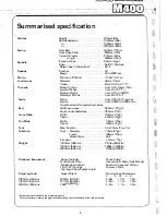
Page 4: ...from 0 04 to 0 71mm rev English from 0 0016 to 0 028in rev Cross Feeds Half Longitudinal Values Width over ways 360mm 141 8in Depth under headstock 380mm 15in Width 195mm 75fuin Travel 250mm 9 8in Width 115mm 41 2in Travel 120mm W 4in Max Section 32 x 25mm P 4 x 1in o uill Diameter 73mm 27 fin Travel 155mm 6 8in Morse Taper No 5 Set Over 1 2mm 1 2in 1000mm 40in crs 1753kg 3857 lb 1500mm 60in crs 1...

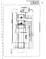
Page 5: ... 1 Jr 2 rT____ _ _ 1 I J I I I l I JU I r I i r I rr _j nr 1 tf1 F _fr l T r _J r_ 1 4 J J r 1 r _ _ _ _ 1 I v r _ _ T I r 0 l l j f I I i I ____ I I j 1 0 I R i i I 1 x I I 1 l j 4 r I 11 1 I I 1 I l f I i 1 r f e I f 1 i 1 s it C 4 i I I I i I ...

Page 6: ... t _ ___ 1n_s_t_a_lla_ t_io_n___ J 3 ...

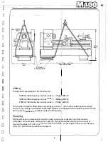
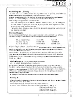
Page 7: ...55 The machine should be lifted using rope slings as shown t with the rear splash guard removed and with the carriage and tailstock assemblies displaced as despatched towards the tail end of the bed to give an equilibrium condition under the lifting hook l Cleaning Bright surfaces are coated with an anti corrosive compou 1 nd at despatch and this must be completely removed using white spirit or pa...

Page 8: ... entry is at the R H side of the control cabinet looking from the rear of the machine and tapped 25m m electrical conduit Line connections should be to isolator terminals and a substantial earth continuity conductor must be connected to the earth tenninal on the panel SEE ELECTRICAL WIRING DIAGRAM Motor direction must be CLOCKWISE looking on driving end SEE DIRECTION ARROW ON MACHINE FRAME Lubrica...

Page 9: ...l i I_ __ f1 fi r i l si 1 L 1 i i I i 1 1 1 I i I Ikl I I Iff1 wr i r1 J a i Lubrication 7 II J ...

Page 10: ... ENEAGOL HYSPIN HEAVY HLP 68 AWS 68 MEDIUM 150 DTE ENERGOL ALPHA a1v EXTRA HP 150 HEAVY ZN 220 150 Check levels and oil daily 2 61 tres a P W L C WLM Schauglas und di taglich Gberprufen g 9 e Shell NUTO TELLUS RANDO H68 68 HD 68 OR A68 NURAY VITREA REGAL 100 220 R 0220 Verifier les regards et graisser quotidiennement 8 31 1 1 tS hV r _ I ...

Page 11: ... t 1 p I _ u I il I r I f l l i l t J l t j ft t I J tr l i J I I r 9 I I I t 4 1 Operation J r ...

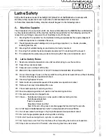
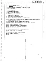
Page 12: ...les 1 Read and understand operation notes before attempting to use the rn achine 2 Keep lathe work areas clean 3 Keep area surrounding machine tidy 4 ENSURE YOU KNOW HOWTO STOP THE MACHINE BEFORE STARTING IT 5 Do not interchange chucks or other spindle mounting items between lathes without checking for correct locking see operational notes 6 Use only high speed chl lcks 7 Note maximum permissible ...

Page 13: ...ting workpiec1 es of the correct safe working load and d d 1 ensure 1t 1s not worn or amage I 11 Stand clear when lifting workpieces or equipmentiby crane k 12 Obtain assistance when mounting heavy or awkwardly shaped workpieces 13 Do not wear rings watches ties etc I 14 Do not keep tools scribers etc l in overall pockets 15 Do not remove guards unless machine is stationafv 16 Do not wash hands in...

Page 14: ... 2 I _ N I r 1 __ lilt n I I 1 II CJ t k J 29 1 Jit S fi IZ n I 28 i i i Ii ...

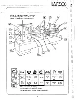
Page 15: ...elease Pushbutton 1 I Coolant Pump Pushbuttons I Hydraulic Pump s Pushbuttons Power Chuck PushbuttorJ Top Slide Lock Screw I Cross Slide Lock Screw I on R H of Crosslide Top Slide Traverse Handl Cross Slide Traverse Handle Carriage Lock Bolt I Tailstock Guill Lock Quill Traverse Handwheel I Tailstock Auxiliary Clamp Bolt Tailstock Set Over Screw I Spindle Control Lever Carriage Traverse Handwheel ...

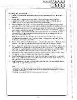
Page 16: ...l feed direction at the headstock lever 3 i e feeding towards headstock and check that the feed reverse lever 29 matches the direction selected 6 Select feed rate by referring to the charts on the headstock and selecting in the sequence listed the appropriate positions on the feed selector dial 1 and levers 2 engagement of the feed gears may be assisted by inching the spindle using the spindle con...

Page 17: ...crew is provided in the rear face of the body Set over adjustment is Jchieved as follows Unclamp tailstock lever 20 and bolt 22 Slacken rear location screw say on half turn then simultaneously slacken one set over screw anc 11 tighten the other until the required setting is obtained Retighten the rear location screw may be disengaged by dulling it outwards from the carriage fac d I d h h h ff d a ...

Page 18: ...ide with the reference line R on the spindle nose This assists subsequent re mounting NOTE For correct locking conditions each cam must tighten with its index line between the two vee marks on the nose Fig 2 DO NOT INTERCHANGE CHUCKS OR OTHER SPINDLE MOUNTING ITEMS BETWEEN LATHES WITHOUT CHECKING EACH CAM FOR CORRECT LOCKING TO ADJUST CAMLOCK STUDS Remove Lockscrew 8 Turn Stud A one full turn in o...

Page 19: ...I i f n u 17 Thread cutting ...

Page 20: ... AR7Y 8 CT1W AT3Y 12 ARGY 9 CT2W AT2Y 11 AR4Y 1 0 BSlW AT1Y 10 AR3Y 1 25 8S3W AS3Z 9 AR2Y 1 5 BS6W ASBY 8 AR1Y 1 75 assw AS7Y 2 0 BT1W ASGY 2 25 BT2W AS4Y 2 5 BT3W M O F ins F mm 2 CR1W 1 2 CT6W 4 0 as w 0016 CR1X 04 225 CR2W 1 25 BS3W 4 5 BS2W 002 CR3X 05 25 3 35 4 45 5 6 7 75 8 9 1 0 1 1 18 _CR3W 1 3 CT7W 5 0 BS3W no2s CR7X 063 CR6VJ 1 4 CT8W E O BS6W 003 cs x 08 CRS 1 1 5 BS6W 7 0 BS8W 004 CS3X...

Page 21: ... l L i s Changewheef Combinations Fig 2A for metric leadscrew machines Fig 2B for English leadscrew machines 4 G H 6 mm pitch Leadscrew H 4 tpi Leadscrew 19 ...

Page 22: ...S1ZF 0 8 CTlWH 24 AS6YH CR1WG 3 6 CT2WG AS1ZG 26 AS7YF 0 8125 BR7WH AS1ZH 0 8125 BR7WF 4 8S1WG 6 5 AS7YG 27 AS2ZF 0 875 8R8WH 26 AS7YH 0 875 BR8WF CT3WG 6 75 AS2ZG 28 AS8YF 0 9 CT2WH 27 AS2ZH 0 9 CT2WF 4 4 CT4WG 7 AS8YG 28 5 BRlZF 1 BS1WH 28 ASBYH CR2WG 4 5 BS2WG 7 125 BRlZG 30 AS3ZF CT3WH 28 5 BR1ZH 1 BS1WF 4 6 CT5WG 7 5 AS3ZG 32 ATlYF 1 1 CT4WH 30 AS3ZH CT3WF 4 75 AT8WG 8 AR1YF 33 AS4ZF 1 125 B_...

Page 23: ...cut Dial numbers at which the leadscrew nuts may be engaged B ENGLISHTHREADS on METRIC LEADSCREW MACHINES or METRIC THREADS on ENGLI SH LEADSCREW MACHINES _ Ollll mm 225 18 15 4 16 1 8 25 16 1 8 4 5 18 15 75 16 1 8 5 20 1357 1 16 1 8 5 5 22 15 1 25 20 1357 6 16 1 8 16 1 8 7 14 15 Hi 16 1357 8 16 1357 1 75 14 15 9 18 15 2 16 1 8 10 20 1357 2 5 20 1357 1l 22 15 16 1 8 12 16 H H 14 15 14 14 15 812 lI...

Page 24: ...which can be cut is limited to figures which can be divided without _a remainder into half the number of teeth on the top Changewheel THEN Number of teeth to be indexed between each Thread start E G No Teeth of Top Changewheet 2 x No of Starts Required For a Two Start Thread index top Changewheel by Or No Teeth on Top Changewheel 4 One whole quarter of a revolution 22 1 i u ...

Page 25: ...i _1 L l fi l l b f_ _ _1 1 J 0 U C l 23 ____J Maintenance i I i ...

Page 26: ...tic Belt Drive to the Lubricant Pump will compensate for any Motor Platform movement and needs no adjustment Fig 1 Fig 2 Spindle Bearings A pre loaded spindle bearing arrangement is incorporated which does not require adjustment Any wear which may take place is automatically compensated Spindle Brake The Spindle Brake is self compensating for wear and should require no adjustment during the normal...

Page 27: ...atrix Slide back Knurled Lock Ring A and rotate one notch at a time in direction of arrow to tighten 3 Lever type Clutch Ortlinghausl Rotate Input Pulley wntil spring tab 8 which locks adjustment nut is accessible prise tab away just clear of slot Rotate nut by qne notch at a time in direction of arrow to tighten 4 Reset locking NOTE OVER ADJUSTMENT MAY CAUSE SERIOUS DAMAGE TO CLUTCHES Fig 3a 25 ...

Page 28: ...ravel at each adjustment to be sure of an even action Note 5 movement of the Adjusting Screw will provide approximately 017mm 007in ta e up of play in the Strip Fig 4 Cross Slide Ways Fig 5 Wear in the Cross Slide Ways must be adjusted for by means of the Taper Gib Strip as follows Turn the Slotted Head Screw on the Front Face of the Cross Slide in a clockwise direction to tighten the Gib the proc...

Page 29: ...t a screw driver into the tapped hole and tum the Captive Adjusting Screw to give the required setting clockwise for positive adjustment Care should betaken to avoid over adjustment sin ce a 90 turn of the Adjusting Screw will provide appr9ximately 017mm 007in take upof backlash Traverse Cross Slide by hand over full tr avel to be sure of an even action Re fit M12 Blanking Screw Recommended workin...

Page 30: ...ite end then re tighten this after adjustment to lock the Gibin its new position Fig 7 Tailstock Bed Clamp Fig al The Angular Lock Position of the Bed Clamp Lever is adjusted by means of the S tf Locking Hexagon Bolt located on the underside of the Tailstock Front Clamp Plate and between the Bedways Turn clockwise to increase clamping action The auxiliary Clamp Bolt needs np adjustment and is simp...

Page 31: ...ETTING DURING NORMAL USE OF THE MACHINE BUT TO CONSl LT OUR SERVICE DEPARTMENT IN THE UNLIKELY EVENT OF A PROBLEM Adjustment may be achieved however as follows 1 Slacken the two M4socket grub screws on the R H O D of the unit 2 Turn the inner adjusting ring clockwise to increase slipping torque by means of the two holes in the R H end face of the unit 3 Re tighten the two M4 Locking screws on the ...

Page 32: ...se potentiometer lock nut on brake power supply unit 2wl and turn adjusting screw anti clockwise as far as it will go 3 Switch on mains supply at the isolator interlock part and press the brakerelease push button at the control station Then using a D C voltmeter 1OOV scale across terminals 25 and 26 on 2w1 or at the brake unit terminals slowly turn the adjusting screw clockwise until the brake dis...

Page 33: ...n td j t L f _J r i J Llf J I 7 r l LJ __ P_a_rt_s_ _s_e_c_ti_o_n __J ...

Page 34: ...ed when other than one is given in a circle fof owing the Part Number itself Where part numbers change with machine bed length then the model number is given vis 11000 1 or 1 1500 1 or Standard Proprietary Parts i e items which can be p urchased from local Engineering suppliersi may be identified by the bracketed letter code included in the Part Number and reference to the appendix at the end of t...

Page 35: ...and Gearing 402 4 Gear Shifting Mechanism 402 5 Gear Shifting Mechanism 403 1 Gear Box Casting if 403 2 Gear Box Gearing 403 3 Gear Box Gear Shifting 404 1 Apron 404 2 Apron Gearing 404 3 Apron Gears 404 4 Apron Pump r 404 5 Thread Indicator Dial i iii 405 1 Saddle 405 2 Slides i i 406 Shafts rack and bracket f I ll 407 Tailstock f 408 Chargewheels Swing Frame 410 Standard Equipment 34 ...

Page 36: ... _ d i I O i I L l LJ 400 4 79 t M8x30 FV D001H2093 D272H1002 M16x75 FH r l M16 FN 35 V 401 1 ...

Page 37: ... X 3 oo f 401 014 M6x10 FS B1210 1 J 401 021 401 029 4 79 36 _ 401 028 Ml0 FL _ M10RH BJ V yf J 001 3 ia0x 49 25LS BRAMMER O y t Od1 401 026 I M10 FL M6x12 FXw 401 2 ...

Page 38: ... I k J Cl J j f 1 1 J le 36050008 ENOTS 401 042 36050108 ENOTSl II 3605042 ENOTS 4 79 r I i 1 I 401 037 0010_ 401 009 37 12 37 i121aa1l 12x1 C_E 401 3 ...

Page 39: ...S 36050007 36051104 36050204 ENOTS 36050004 402 044 057 6x2 A RM Q 402 019Q 7 75 36054122 l 36054 003 34015 603 ENOTS 36050 108 36050 008 101 M3x6 FRlT lll16 NTI M6x16 FYXJ 402 070 402 066 030 34x2 HDU 12 B S P FP 38 402 1 I ...

Page 40: ... A j 7 70 402 15 4 l0 x32IKS MBx3 FY 39 30 3 x O DUl S90M1BISALTER K 02007 02 0 0 t AL 5 l lM 8 S 0 LTERI 6 4 4 2 CEl l C _ QL id 402 040 02 0 3 402 2 ...

Page 41: ... i J l IL OllO onvL c ccbS n g ll ooa CJ 402 058 B SG373 A C i1 2 CEJ 30162X 0 16 08J 79 k ___ 40 02 01 52T 0602H0410 1 l 0 ovr 6 01 tc 5 2CCEl LA Q 35r 39 30 DU bf tp BR3911HA f_ C D M8x20lFXdl 402 3 I 1 J ...

Page 42: ...i 1 t kj jl r l 1 id In_ _ l J i lJ f d u l 1 C 1 t 7 o d 402 074 7 76 402072 401 024 41 Ml2 12 FXwi a acsa sG395 F or1 c t 0 402 145 402 078 MB x16 FR 015 6 x 24 RM 402 073 402 062 402 4 ...

Page 43: ... J f iii 0 1 CJ1 SP999 M16 40 07 ol 5x26 IHTP 16x1 CE e1 x1 CEl 403 0 53 m 402 099 7 402 104 402 092 M8x16 FR SS 402 110 72T 402 102 r I S P 999 M16 p r e 24 1 2 CE M8x12 CFRl r _ j ...

Page 44: ...M6 FN CTI C23 Ci 2 ml 77 403 001 403 003 lj4 B S P PLUG J 31 B S P 45 ELBOW f _t j l a ii 41 5lt3 RM 0 00 406 fJ M3x6 FR T I 1r t j _ E 1 SI o 25 26x25 DUI 403032 o Ol 045 403 046 029 1xl 6 RM 30x6 SF 403047 1 1 CO SI q Cb o F7 1 Ai ...

Page 45: ... 039 019x1 21CEJ 4 79 s o a 403 008 t25 47x12 BB f 2D 47x141BB 25 47X 218B1 403 014 6x9xo2 i1xwJ ________ 44 j 25 47 12 88 e12 14x15 DU Y 30S SF 403 044 30x1 31CE2 6 25 47x121BB 625x1 31CR2 r J tR OOO H2075 403 2 ...

Page 46: ...t 1 l 4 79 403 050 403 051 A03 058 SP 996 M12 1 L D4o t 45 SP996M12 j 03 053 403 3 ...

Page 47: ... t O l C ii 0 SG 38 4 ju s AJ M10xo 12 c80 FU CM 001 1208 MlO M3 c6 FRJT 1 J J I SEE 404 3 1 asPr FP 2 PH019 _441 1 c PH019 r0ws l I ...

Page 48: ... 0 C 1 c t 0 t C J C B C Z S 1 l _ t J S 23 i E 3 1 4 r J cm iz L D L S7I 3 1111 6 x2 4CRM 404002 420 4 062 V il l 3 M10x12 80CFU M10x 25CFV 0 J t iv I i ...

Page 49: ...i I fl l bl f j j n r t j 2 0 i e16 18x20 0Ul 4 79 IL A 62ro 8 9x 221KW 40 058 47 t M5x16 FY L AXK 2542 C1NAI AS 2542 CINAI 404 2 ...

Page 50: ...tl t 0 w rr 404 043 404 051 p 13 1 X 1 6 R M 3x ixe13 KW _ fu _ we J51DX iJ30 37x4 SMl e57 6x2 4 RM 2 24 6x 2 RM 6x16 HTP ___ 5 x 16 HTP so 378 Z 1 404 010 l o 7 ...

Page 51: ...J l u 7 76 0116 2 RM 36C530 02 ENOTS 36 050l 02CENOTSJ o oo p4mm Nr PH003 __ J04H09 ____ i6 asP wc i71SB __ 360 l7fJ0D EtlOTS t1S SBI 04x6 GP1J ____________ __30 150 M8x16 FXd 0216 2 RMI 013624 RMI 304151 SG3 2 304 152 72 18 l CBI 404 4 49 ...

Page 52: ...M8 Fl 1ETRIC J0 4 111 7 16 50 813 30 4 160 304 162 404 5 ...

Page 53: ...61528 4 NADELLA 010 2 18 8 0S r L Oif O 405005 0211H2003 M xd 0x70 FU J 6D O I C2 Wt 70 2J 1 2 _ Q 6 ON 405016 02 RH c m t 1 405015 E fH 4050 Ji 73 405 0 d J F 05072 I Ml2 WN Ml0 90 FY 405071 405070 w 7V M5x12 FSlS S 405 D67 M12 20 F __ 405 066 Xc L 40 065 405 068 M8x16 FR 405064 M8 WN MBx35 FHl uN ...

Page 54: ...01_1 405 2 7 76 e C0 1 M 20 FHl 405 052 Slll C Oe o 0 013H 5001 METRIC 0 Ol3H5002 ENGLISH 0 70 Pr 0 p 013 I om 05 012 g 19 1x1 6 RM _ o o D f J OIi b M 5x20 F Y F l ooor sG 344 l OQOlc 6 SBl Q 52 405 2 ii t ...

Page 55: ...D S fAS25 42 1NA 2 AXK2 42 1NA 1 _ 403 034 406 002 METRIC 406 003 ENGUSH 406 007 METRIC 406 008 ENGLISH 0602 METRIC 1 z_ os 026 ENGLIS 0 6x40 HTP i 32xl 5 CE 406 021 CJ 406 0Tl M 40 012 1 5M 40 029 d E cJ 8D 08X36CI ITP Q M6X30 FY r 406 013 1204 SKF Z 2 8 20 23x25 0Ul J51204 SKF x 71_1 __ a ...

Page 56: ... rJ r _ 407 00BCMETRICl 407 009 1oNGLISH M20 FN1 M20 WN ia LIIIIZD _ c _e ztXL__ 0 407 004 METRIC 407 005 ENGLISH 407 003 7 xr ...

Page 57: ...i J 7 76 rss Q 406003 18 i20 x20IDUl 8 026 2BTI 40 0044 i44 T PITCH 4 0 S OA6 48Tl METRIC 6mm a 05s 56Tl 406 066 66r OB l 2TI OB 072 5 96T l OB 09 O t n I o a a 4BT l ENGLISH 4 T P l l 4 0 6 156T l 406 g B BBTJ gtos5 19sr l 408006 408 ...

Page 58: ...x15mm WRS Tt o n 0 M10117mm xM12 l9mm WRS il q Q M14t22mm X M16 24mm WRS r1 Q 0 _ _ 410 001 MW Cmrr X M24 3 mm WRS T6 o iI0 o ___ 0 5MT Wll10 TI 25mm FK 56 3mm FKJ mm FIO 5 mm FKJ 6mm FK Bmm FK WRS lb or 0 4 U I 10 020 410 ...

Page 59: ... Slide 411 16 American Toolpost 411 31 Perspex Chip Guard Saddle Mounted 411 35 Coolant Assembly 411 38 M C Lighting 411 41 Travelling Steady 411 42 Stationary Steady 411 45 48 Bed Stops 411 67 Power Drilling Attachment 412 Taper Turning Attachment 419 Bed Stop 6 Pos_ition Longitudinal 411 065 66 Dual Reading Dials 413 Bed Capstan Unit 414E High Speed Threading Attachment 414M High Speed Threading...

Page 60: ...406 040 406 046 406 047 M6x12 FXdlL M10x130 Fsl 406 045 406 043 406 044 _ M6x12 FXd L 6 0N rJl 6 19x6 BB2l 0 6x 6 CR 406 052 406 050 406 051 406 042 406 04_1 M4x10 FS _ 406 2 58 1 d r i j ...

Page 61: ...410 012 _ I r 1 m _ i 1 21 410010 f l l u 10 015 lfJ 20 FY g__ _ x32 1HP A 410 013 Q SG382Q ij lv112x12 FXw CT 59 804SA MICROLIMIT 410 011 410 2 _ I ...

Page 62: ...0 0 r irJ cf Metric 411 050 r66 0N 411 177 411 180 411 179 411 17 M5x10 FXd 411 176 0 1 15 x6 PD c 1 Ai 0 _ t J rd lfIJfe 411 187 __ 411 188 2 rz 7si 411 182 06 ON A pl o English 411 051 _ _ 1 w ...

Page 63: ...s lll t i j t j n 1 l w 411 065 411 251 40500 D211H2003 M6x50 FY D220H1010 4 79 411 255 M5x16 FY 61 411 263 M8x20 FVJ G r i i J 405 033 LS1226 1NA 411 243 M5x16 FHl 411 233 c AXK1226 NA 2 A l226 1NA Q _ 161 411 066 ...

Page 64: ... 411 297 rj rI SG404 411 272 2 4 0 vA 4i1 r lJNS 411 273 71 rl ll 2 4 79 411 278 t 2 I L1 62 411 270 4 a l M10 x30 Frl FOR SLOTTED TOPSLIDE Q o t 0 i b r 1 t ...

Page 65: ... Li l 1 h p1 i J 411 322 411 11 13 4 79 O O I 1sr 411 329 ij M8x20 FV 2 63 411 331 411 324 411 320 411 325 SG403 l_ 411 11 x 4 411 029 TA OI 2 o 411 13 I ...

Page 66: ...M20 FH A 02O WN 411 028 1 411 025 4 11 026 411 14 64 J ...

Page 67: ...r 1 r J M16x60 FJJ 411 013 65 411 012 411 010 411 011 411 16 ...

Page 68: ...__ 411 052 66 411 050 41i Q53 411 31 i I J 1 t 1 I ...

Page 69: ...L i r8 f I 1 l J b t 1 1 J A8970015 INFLEX TY28MCTYRAP J STATE SUPPLY VOLTAGE 4 79 1 0 003 0 SNP14 INSULOIO 67 1 1 f fl i M5x25 FYJ D660H6003 411 080 411 35 ...

Page 70: ...M5x16 FS 411 085 68 160WATT 50VOLTS l40WATT 125 VOLTS 5mi 50VOLT OR 25VOLTS o o s 411 38 l l 1 I I l I 1 fYi_l I r r I li _ i I I_ i I ...

Page 71: ...C I J p t CJ 411 131 69 411 133 411 136 R A22 8 2RS INA g 411 135 411 100 M12 WN g M12x70 FD1 6 411 41 ...

Page 72: ...411 129 411 1261 1 411 131 3 4 3 1 t J f CJlJ t t SO 70 4i1 134 Q 411 137 Jj V A r i 411 42 r I I r 1 _I J 1 r_ _ 1 1 ...

Page 73: ...i9tt N ETR1Cl j 411 162 j 0220H1012 411 47 0111H4007 00 r D512H0005 M10x 12x3Q FUl jJ 0512H0001 f1 M6J 2 D5l2H0004 D512H0003 71 l j i r T 1 0250H102 lMENEG TRJC LISH 0250HOOO M10x40 FYl D120H100I M10x40 FY V 411 46 41 152 411 48 M15x20 FYi 411 150 SG347 0200H0015 D831H3001 411 45 411 45 48 ...

Page 74: ...411 200 411 202 M10 Fll 411 205 0401H0001 72 411 204 M10x35 FY 3 411 67 ...

Page 75: ...i L Q J l I I j L i 1 D j M5x20 FY 412001 412 023 4 79 412 006 73 w M4x10 FV I 412 005 ______412 008 4 2012 I 412 014 l I 10 o FYI 010x45 PD 412 l i l I ...

Page 76: ...M16 FH 413 035 ti 413 033 M6xl0 FXWl A 413 036 413 042 413 024 ll4x25 PT 413 00 4 PH006 413 005 413 l ll 74 ...

Page 77: ...1 013 SG36 M8x30 F Y Q A ti6x25 HTPJ 414 045 SG363 6S3673 2 0B0MS CR 0 I PH007 414 047 41 4 046 31i esF FLl e 414 035 0 Ii 414 044 M6 10 FYl y i 41 036 M ix10 FS 4 414 051 75 Mex60 FO ni MBx20 FYJ 414_031 3 FLJ 9 t SG 364 28Ax 4 FX 114 041 414E ...

Page 78: ... 108 il6x2 5 HTPl BS367J 2 080MS CR J asF FLJ Cf 414 136 O 414 137 Ii 414 144 M6x10 FYJ W 414 140 414 138 76 _ v2cx x LJ1 M o lll6 WS 2 A WS M6x30 FYJ I V 414 111 414 103 M 414_ jQ4 1 5M 414 005 2M 414M 1 ii r 1 1 1 1 I L ...

Page 79: ... MBx30 FY t J i __ 2 419 015 419 016 M6x20 FY 7 __ x12 _ SHORT MB FL J 1 8 1 LONG i Jt 419009 1 3 x22 MBK r 419 023 419 013 E 3 t Q i 1 r z MBxB FXw S f 402 6 SB 1 re ll___ c l f j M8x25 FY 3x5x 1 13 KW PH022 6x32 MBK M8x30 FY Q 419 003 c iJ E D ci ...

Page 80: ...Head Screw Bolt Standard Hexagon Nut Locknut Suffix 8 8 for Hig Tensile Types Suffix L for Self Locking versions of the above Hammer Drive Screw Wing Nut Domed Nut Castle of Slotted Type Nut Nylon Ring Locking Nut Thread Inserts Tll Tl2 I Press in Type Thread Insert Coil Type Thread Insert Washers WN WL WK ws WSs WC WF DS Bright Washer Normal Diameter Large Diameter Crinkle Wavy Washer Spring Wash...

Page 81: ...ier I I I I I I I I I Sintered Bronze Bush Ball Roller Bearings BB Std Ball Bearing 881 Std Bal Bearing with Shield or Seal one side 882 Std Ball Bearing with Shield or Seal both sides 883 Std Ball Bearing with Snap Ring BBT Angular Contact Bc 1II Bearing RB Cylindrical Roller Bearing For Needle Roller Brgs Needle Thrust Races Ball Thrust Brgs and Taper RollerBearings Manufactuers Name is Quoted a...

Page 82: ...n Wrench Key HP P V C Hose HC Hose Clip PP Plastic Plug WRS Standard Spanner EB Eye Bolt ow Oil wick CT Copper tube NT1 Nylon Tube Natural NT2 Nylon Tube Blue NT3 Nylon Tube Green NT4 Nylon Tube Red Conventional Description Given Norn Shaft 0 0 D and Width Manufacturers Part No Internal 0 of Ring and Section0 Manufacturers Part No Norn Hole0 Thread details Norn Outside 0 Norn 0 X Length Manufactur...

Page 83: ... LJ l J t f 1 I i 1 i J r s 0 i _____ _II j 1 J J 9 8 9 0 5 i 1 1 l s s I r i ...

Page 84: ...M400 202300 NOTES Customer Service Parts and Sales call 800 575 2843 fax 888 839 6434 info harrisonlathe com www harrisonlathe com ...

Reviews: