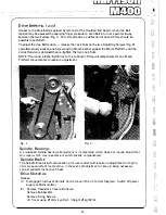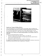
MOUNTING OF CHUCKS, FACEPLATES and other
SPINDLE MOUNTED ATTACHMENTS
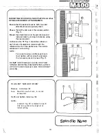
Ensure
that the location faces on both nose and
attachment are scrupulously clean.
Check
that all the cams are in the release position
(Rg. 1).
Mount
the attachment on to the spindle nose and
lock each cam by turning it clockwise using
the key provided.
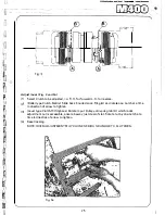
A reference line R1 (Fig. 1) should be scribed on
each chuck or faceplate to coincide with the
reference line R on the spindle nose. This assists
subsequent re-mounting
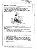
NOTE:
For correct locking conditions each cam
must tighten with its index line between
the two vee marks on the nose (Fig. 2).
DO
NOT
INTERCHANGE CHUCKS OR OTHER
SPINDLE MOUNTING ITEMS BETWEEN LATHES
WITHOUT CHECKING EACH CAM FOR CORRECT
LOCKING.
TO .ADJUST 'CAM LOCK STUDS'
Remove Lockscrew (8).
Turn Stud (A) one full turn, in or out
as required.
Re-fit and tighten
lockscrew ( 8).
NOTE:-
A datum ring (C} is marked on each
stud as a guide to the original or
initial setting.
16
____
,_,
__
....
�
( __ s_-P_i_nd�l,_;_..e_N_· o_s_e ___
.
�)
,, ,l
- \\?;
liJ
1
\:1
@.
r
Summary of Contents for M400
Page 1: ...420mm 16 1 2 heavy duty centre lathe Operations Manual info harrisonlathe com 800 575 2843 ...
Page 6: ... t _ ___ 1n_s_t_a_lla_ t_io_n___ J 3 ...
Page 14: ... 2 I _ N I r 1 __ lilt n I I 1 II CJ t k J 29 1 Jit S fi IZ n I 28 i i i Ii ...
Page 19: ...I i f n u 17 Thread cutting ...
Page 25: ...i _1 L l fi l l b f_ _ _1 1 J 0 U C l 23 ____J Maintenance i I i ...
Page 33: ...n td j t L f _J r i J Llf J I 7 r l LJ __ P_a_rt_s_ _s_e_c_ti_o_n __J ...
Page 36: ... _ d i I O i I L l LJ 400 4 79 t M8x30 FV D001H2093 D272H1002 M16x75 FH r l M16 FN 35 V 401 1 ...
Page 46: ...t 1 l 4 79 403 050 403 051 A03 058 SP 996 M12 1 L D4o t 45 SP996M12 j 03 053 403 3 ...
Page 52: ...M8 Fl 1ETRIC J0 4 111 7 16 50 813 30 4 160 304 162 404 5 ...
Page 66: ...M20 FH A 02O WN 411 028 1 411 025 4 11 026 411 14 64 J ...
Page 67: ...r 1 r J M16x60 FJJ 411 013 65 411 012 411 010 411 011 411 16 ...
Page 68: ...__ 411 052 66 411 050 41i Q53 411 31 i I J 1 t 1 I ...
Page 74: ...411 200 411 202 M10 Fll 411 205 0401H0001 72 411 204 M10x35 FY 3 411 67 ...
Page 83: ... LJ l J t f 1 I i 1 i J r s 0 i _____ _II j 1 J J 9 8 9 0 5 i 1 1 l s s I r i ...

