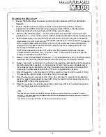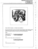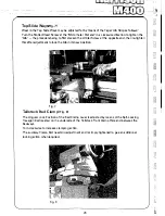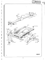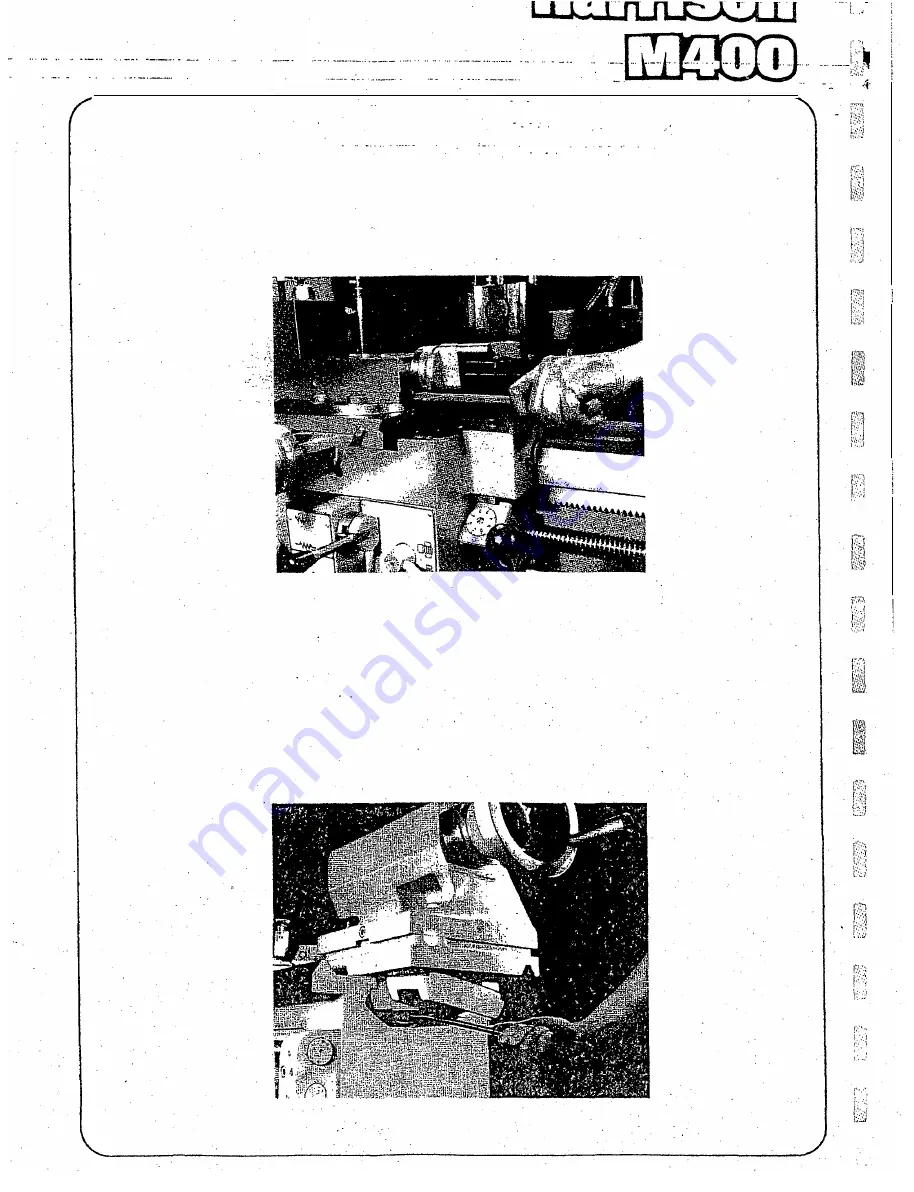
. Top-Slide Ways<fig .. 7r
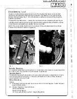
Wear in the Top Slide Ways may be adjusted for by means of the Taper
:..
Gib Strip as follows:
:..
Tum the Slotted Head Screw at the 'Micrometer Dial end' in a clockwise direction to tighten the
'Gib' - the procedure being to first slacken the similar Screw at the opposite end,then re-tighten
this after adjustment to lock the Gibin its new position.
Fig. 7
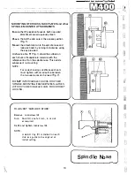
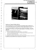
Tailstock Bed
Clamp
(Fig. al
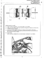
The Angular Lock Position of the Bed Clamp Lever is adjusted by means of the S�tf-Locking
Hexagon Bolt located on the underside of the Tailstock Front Clamp Plate and between the
Bedways.
Turn clockwise to increase clamping action. ·.
The auxiliary Clamp Bolt needs np adjustment and is simply tightened to give an additional
locking action when required.
Fig. 8
28
, .. J
::,,.,\
j/.'
rJ
Summary of Contents for M400
Page 1: ...420mm 16 1 2 heavy duty centre lathe Operations Manual info harrisonlathe com 800 575 2843 ...
Page 6: ... t _ ___ 1n_s_t_a_lla_ t_io_n___ J 3 ...
Page 14: ... 2 I _ N I r 1 __ lilt n I I 1 II CJ t k J 29 1 Jit S fi IZ n I 28 i i i Ii ...
Page 19: ...I i f n u 17 Thread cutting ...
Page 25: ...i _1 L l fi l l b f_ _ _1 1 J 0 U C l 23 ____J Maintenance i I i ...
Page 33: ...n td j t L f _J r i J Llf J I 7 r l LJ __ P_a_rt_s_ _s_e_c_ti_o_n __J ...
Page 36: ... _ d i I O i I L l LJ 400 4 79 t M8x30 FV D001H2093 D272H1002 M16x75 FH r l M16 FN 35 V 401 1 ...
Page 46: ...t 1 l 4 79 403 050 403 051 A03 058 SP 996 M12 1 L D4o t 45 SP996M12 j 03 053 403 3 ...
Page 52: ...M8 Fl 1ETRIC J0 4 111 7 16 50 813 30 4 160 304 162 404 5 ...
Page 66: ...M20 FH A 02O WN 411 028 1 411 025 4 11 026 411 14 64 J ...
Page 67: ...r 1 r J M16x60 FJJ 411 013 65 411 012 411 010 411 011 411 16 ...
Page 68: ...__ 411 052 66 411 050 41i Q53 411 31 i I J 1 t 1 I ...
Page 74: ...411 200 411 202 M10 Fll 411 205 0401H0001 72 411 204 M10x35 FY 3 411 67 ...
Page 83: ... LJ l J t f 1 I i 1 i J r s 0 i _____ _II j 1 J J 9 8 9 0 5 i 1 1 l s s I r i ...

