Sauter flexotron®800
ventilation
Functional description
P100012082
38
on and off times can be set, i.e. the minimum time the step has to be inactive or active
for a change to occur.
Binary
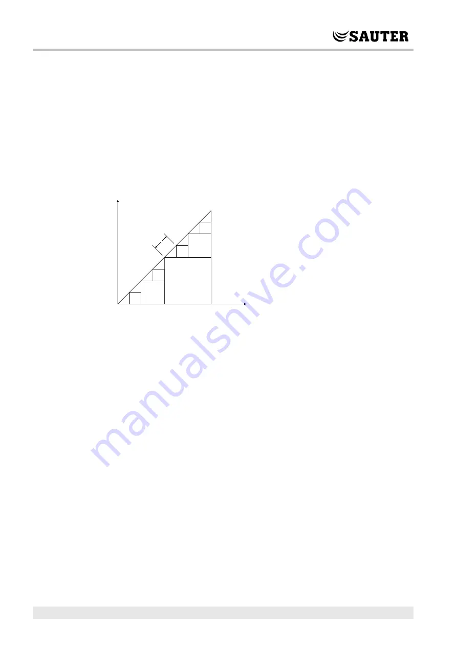
The heater power outputs should be binary weighted (1:2:4:8 for heating, 1:2:4 for
cooling). The number of loads to be controlled is set. Thereafter the program will
automatically calculate the individual activation levels. Switching differential and
minimum on/off times can be set. The number of heating steps will be: 2
no. of groups
-1. In
binary mode, the analogue output signal may be used to fill out between the steps. The
signal will g
o 0…100 % between the activation of each step. The load connected to the
analogue signal should have the same size as the smallest of the binary groups. In the
example below there are 4 heater groups (1:1:2:4) and the total number of heating
steps is eight.
Step controllers and Change-over
The digital output signals "Heating/cooling step 1", "Heating/cooling step 2" and
"Heating/cooling step 3" are used for step controllers during Change-over control (see
section 5.1.12). They have the same functions as other step controller outputs, but are
set to either heating or cooling depending on whether heating or cooling is required.
DX cooling with room or extract air control
If DX cooling is used in conjunction with room temperature control or extract air
temperature control, there are two configuration alternatives, DX cooling or DX cooling
with exchanger control.
DX cooling without exchanger control
When running cascade control, the supply air controller setpoint is normally controlled
by the room/extract air controller output signal.
When DX cooling is activated, the cooling controller setpoint is lowered to five degrees
(adjustable) below the setpoint given by the room/extract air controller. This prevents
the DX cooling from being activated/deactivated too often.
1
1
1
1
2
4
2
Y1 = 1


