42
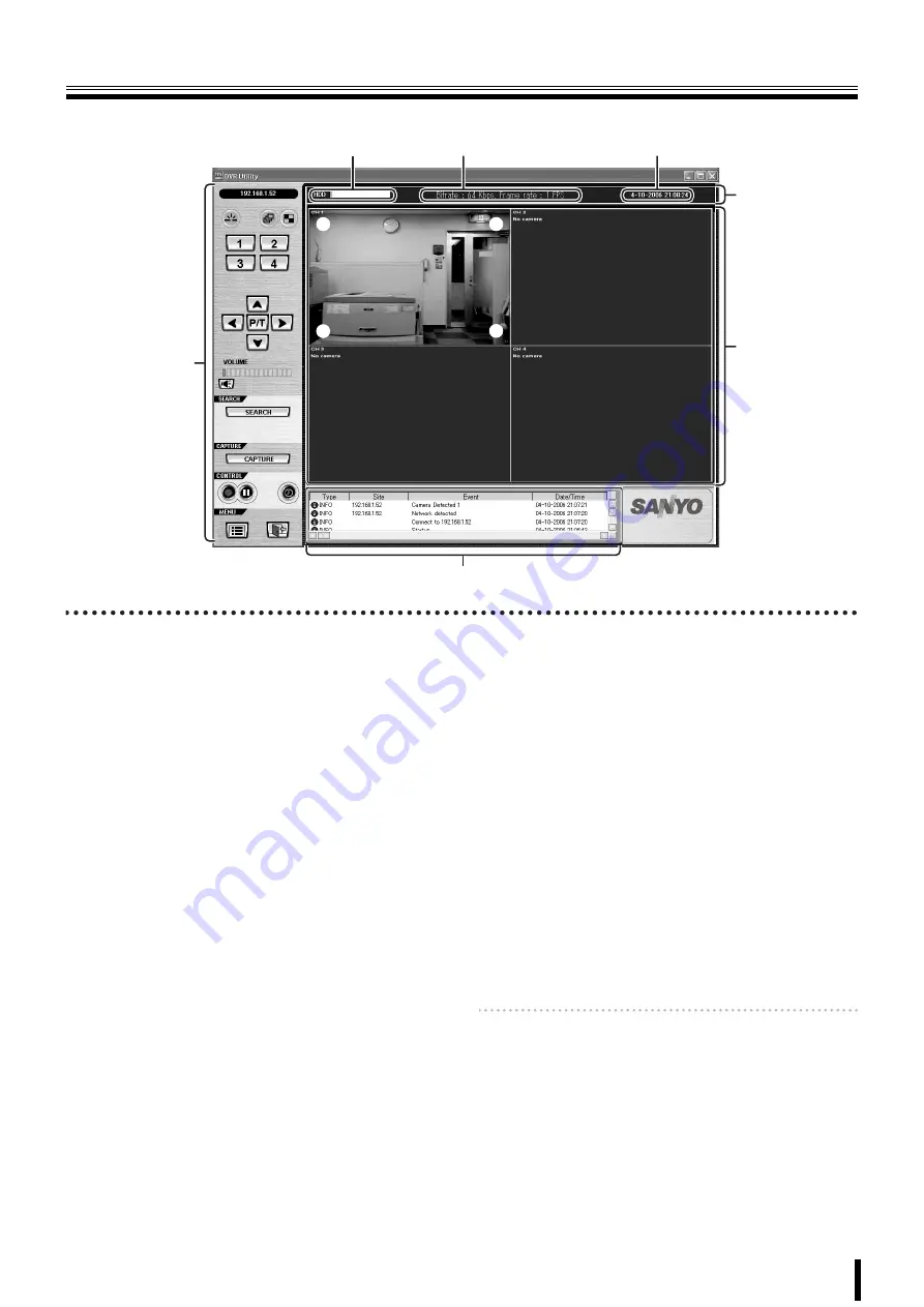
Main screen structure and function of each part
When connected to this unit, the live video of the camera is displayed on the main screen.
1
Video display area
Displays live video or playback video.
<Screen display method>
Can be switched using the operation button on the screen.
(P43)
• Single-screen
• Quad-screen
• Sequence (camera switch) display
• Full-screen display
<Camera information>
The following camera information is displayed on each
camera video.
1
(Top left):
• Camera channel (CH 1-4)
• Camera designation
Set in the
camera designation settings (site)
screen
in the set up menu. (P51)
(When no camera is connected to the channel, the
message "
No Camera
" is displayed.)
2
(Top right):
M:
BY MOTION recording in progress (P13)
S:
BY EXT. SENSOR recording in progress (P14)
3
(Bottom right):
R:
Recording, such as real time recording, in progress.
(P12)
4
(Bottom left):
A:
Alarm output in progress (P43)
2
Information display area
The following information is displayed.
1
Shows the used capacity of the hard disk of this unit
2
Communication bit rate and frame rate
To display, set in the set up menu in the general setting
screen. (P50)
3
Date and time information
For live video:
Current date and time
For playback video:
Recorded date and time
3
Operation panel (P43)
The view operation buttons are arranged on the panel.
4
Log window
The operation history is displayed as a list.
Displayed items:
Type, Site, Event, Date/Time
Memo:
Click [SEARCH] on the operation panel to switch the
screen to search mode. One part of the operation
panel display and one part of the log window display
change. (P47)
1
1
4
2
3
2
3
1
2
3
4
(The example shown is a quad-screen display.)


