background image

59

60

Usage of each feature

Usage of each fea

ture

Usa

ge of ea

ch feature

SYSTEM MENU

      SYSTEM

Supplement

●If the operation does not return to normal after calibration, 

  contact Sanwa Service. 

CALIBRATION

●Due to wearing and tearing of the internal mechanical elements 

  over the usage time, the neutral position and the operation angle 

  might become off. 

  In such case, you can correct the neutral positions of the steering 

  and the throttle and the operation angle.  

1)Select [SYSTEM] with the multi-selector and determine 

   with the Enter operation.

2)Select [CALIBRATION] with the multi-selector and determine 

   with the Enter operation.

3)Select a channel to calibrate with the multi-selector and 

   determine with the Enter operation.

4)When selecting [STEERING], operate the Enter with the steering 

   wheel in neutral, then operate the steering wheel fully to left 

   and right. 

5)When entering the range, [OK] is displayed. Operate following 

   the display.

6)When calibration is done, [Executed] is displayed. 

7)If the throttle side also needs calibration, refer to the steering 

    to set. 

*Unless necessary, do not set up calibration. If the setting is 

  not done properly, it may not operate normally.
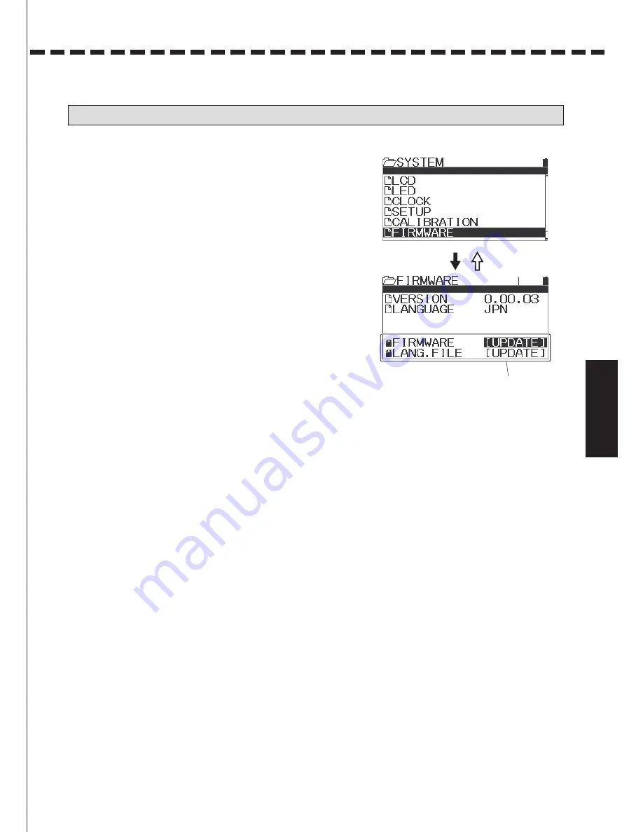
FIRMWARE

●You can check the firmware version installed on the main body unit 

   and the language file, and run updating. 

1)Select [SYSTEM] with the multi-selector and determine with 

   the Enter operation.

2)Select [FIRMWARE] with the multi-selector and determine 

   with the Enter operation.

3)When updating the firmware and the language file, download 

   the data file onto the micro SD card to proceed.


ENTER

BACK

ENTER

BACK

ENTER

BACK

Select Yes, if it is OK.

Calibration complete

YES Selected.

Unless you insert 
a micro SD card, 
it will not be displayed. 

ENTER

Summary of Contents for MT-44

Page 1: ... 90478 ...

Page 2: ...ormance or malfunction and it can be dangerous If the receiver or a servo sinks in the water immediately collect it and dry the interior When the interior is dry please submit it to the Sanwa Service for inspection even if it performs normally The receiver is a precise instrument Please do not add a strong impact or vibration Use a thick sponge to prevent vibrations When installing the receiver on...

Page 3: ...perator registration agency Be sure to install a muffler sound absorber with a silencing effect on an engine car Don t start engine early in the morning Please make sure to clean the location used for operation before you leave Don t use this RC system for other than model use When exhaust gas or fuel of the engine is on the product wipe with a soft dry cloth When the product is heavily stained so...

Page 4: ...el tower blocking the direction of radio wave transmission can cause reduction of operation response or loss of control Always operate within the range you can visually check Don t grab the transmitter antenna Doing so can be dangerous since it can weaken the radio signal output and narrow the range of operation Don t attach any metal parts around the antenna of the transmitter If you have the tra...

Page 5: ...Offset OFFSET 32 Throttle Type TH TYPE 32 AUX AUX 33 36 Step AUX STEP AUX 33 Point AUX POINT AUX 33 4 Wheel Steering 4WS 34 Motor On Axle MOA 34 AUX Mixing AUX MIX 35 Code AUX CODE AUX 36 Timer TIMER 37 39 Setup SETUP 37 38 Lap Timer LAP TIMER 38 Interval Timer INT TIMER 39 Down Timer DOWN TIMER 39 Telemetry TELEMETRY 40 44 LOG LOG DATA 40 Telemetry Setting TELEMETRY SETTING 43 Graph Setting GRAPH...

Page 6: ...SW 2 Function LED Trim 3 TRM 3 Dial Push Switch 1 SW1 Display Panel Carrying handle Movable Multi Selector Back Button Select Button LED T LED will be on when Telemetry is ON and Receiver Battery is OFF LED will be flashing while Telemetry alram is active Names of each part of the transmitter Names of each part of the transmitter ...

Page 7: ...ch Trigger Position Adjusting Screw Grip Normal Small Micro SD cover Antenna interior Throttle Trigger Connector Cover Remove the screw attach the hook and tighten the screw F Make sure that the hook is facing the right direction Names of each part of the transmitter ...

Page 8: ... B Receiver RX 482 DC3 7 7 4V 7 1g Item Weight TX 471 Instruction Manual x1 Receiver Dust Cover x 1 Switch Harness x 1 RX 482 PC Primary Component RX 482 Pleasecheckwhat sincludedbeforeyouruse Structure of the Set Structure and the Standard of the Set 5 Transmitter Receiver Servos Set Specification Structure and the Standard of the Set Strap Hook x 1 Trigger Angle Spacer x 1 Brake Trigger 1 2 x ea...

Page 9: ...ng TH trigger tension By inserting a hexagon wrench driver 1 5mm to the place where the arrow is pointing at in the illustration on the right and turning you can adjust the tension of the steering spring The spring tension is the softest at the time when the product is shipped out from the factory As you tighten with a hexagon wrench driver 1 5mm the spring tension will be hardened 6 Grip Pad Norm...

Page 10: ...ly beyond the range it can cause malfunction Once you set the trigger position tighten the fixing screw and adjusting the trigger is done Be careful with the direction of turning the screw because the trigger position is set at the furthest point of theAside at the factory By switching the angle spacerA B C it is possible to adjust the angle of the throttle trigger to five steps 1 Remove the fixin...

Page 11: ...d close tightly About the optional battery MT 44 is compatible to Micro SD Cards By using a Micro SD Card it is possible to save model data and telemetry data Also it is possible to do firmware update using a Micro SD Card when a firmware update of MT 44 is released Before using 3 Fix the bakre trigger by the screw After inseting micro SD card into MT 44 the file mnamed MT 44 is made and the folde...

Page 12: ...tect the reception part 3 cm from the top of the antenna make sure to place the antenna in the antenna pipe as shown in the right illustration so that the top of the antenna is not exposed outside of the antenna pipe Don t bend the antenna reception part or the antenna coaxial cable because breaking can occur inside Don t pull the coaxial cable forcefully It may damage the receiver interior Instal...

Page 13: ...make sure to take measures for vibration proof and waterproof Negligence of taking these measures can cause runaway When installing the receiver keep the receiver away from a carbon chassis and metallic chassis If metal parts installed on an RC car touch each other it can cause noise that affects reception performance and it can cause runaway Make sure to install a noise killer condenser on the br...

Page 14: ...tle trigger or a switch is operated In case you do not use them turn the power switch off Enter Multi Selector Down Multi Selector Up The cursor moves upward The set value increases Moves the cursor downward The set value decreases Select Selects a channel or feature Back Cancel Goes back to one step before Cancels the setting Multi Selector Back Button Select Button Display Panel Key operation Pe...

Page 15: ...o RX461 or RX462 using combination of RX461 RX462 and SUPER VORTEX or SV PLUS series and turning the Telemetry feature on data is sent to the transmitter and it is displayed on the Telemetry Screen If effect or function is active icon will be displayed Timer Each Telemetry data Log Name Model Number Micro SD card Telemetry Racing Mode Battery Indicator Clock Timer Trim Log Timer Top Screen Telemet...

Page 16: ...is set with the Custom List within the System P 53 CUSTOM Various timer setups and lap display menu P 37 39 TIMER P 19 P 20 P 21 24 P 25 P 25 28 P 29 30 D R SETTING SPEED CURVE F S BASE TRIM P 49 50 P 51 52 P 56 P 56 P 57 P 58 BIND SYSTEM KEY ASSIGN BUZZER BATTERY LCD SETUP P 57 LED P 54 AUX TYPE P 59 CALIBRATION P 55 R MODE P 60 FIRMWARE P 58 CLOCK P 53 CUSTOM LIST P 47 P 45 P 46 P 48 SELECT MODE...

Page 17: ... run and Quick Setup is a feature for various setup with easy operation when setting up a new RC car Quick Setup feature is set in the following order using the Enter operation after launching Selecting Model Selecting Type Initializing Model Selecting RF Modes Selecting Response Mode BIND Setting Base Direct Model Select 1 Turn the power switch on while pressing the Back button 2 Selecting Model ...

Page 18: ...tting up Type Setting range EP CAR STANDARD EP CAR LED UNIT EP CAR SVZ EP CAR SVD GP CAR STANDARD 1 5 GP CAR DUAL BR1 1 5 GP CAR DUAL BR2 CRAWLER 4WS MOA Default EP CAR STANDARD Channel operation of each type will be as follows Select a type to be used according to an RC Holding Power Switch ON ENTER BACK ENTER BACK ENTER BACK ENTER BACK Channel operation specifications for each Type EP CAR STANDA...

Page 19: ... the screen changes to BIND Set up Screen Follow the screen message and start Binding 9 When Binding BIND is done the screen changes to the Base Set Up screen Complete setting for each channel refer to P 25 28 10 When Base setting is done Set Up Wizard will end If you press the Enter button the screen changes to the Top screen ENTER BACK ENTER BACK ENTER BACK ENTER BACK Please note that the analog...

Page 20: ...re precisely by adjusting dual rates of the throttle side When AUX1 AUX2 are set to CODE5 CODE10 setting change of D R will not be reflected to the performance 1 Select features ST TH H L AUX1 AUX2 to adjust with the Select key 2 Determine the feature to adjust with the Enter key and adjust the setting rate with the multi select key 3 Adjust the valus of DUAL RATE by multi selector 4 During operat...

Page 21: ... operation is not recommended Steering speed can minimize unnecessary operation and enables smooth cornering When steering speed and steering curve are combined the effect is doubled Supplement For driving an RC car throttle operation that suits the movement of the RC car is important and excessive operation is not recommended Throttle speed can minimize unnecessary operation and enables smooth pe...

Page 22: ...if you find your RC car oversteering change the setting to the minus side and if you find under steering change to the plus side Steering Exponential is a simultaneous setting for L andR 1 Select ST with the Select button and set CURVE TYPE of ST to EXP with the multi selector 2 Adjust the setting value with the multi selector Setting range 100 100 Default 0 When cancelling a selected feature use th...

Page 23: ...feature of AUX1 from Mild to Linear to Quick You can set the High end and the Low end separately When setting AUX1 to CODE5 CODE10 in AUX TYPE changing the setting does not affect the performance 1 Select AUX1 with the Select button and set CURVE TYPE of AUX1 to EXP with the multi selector 2 Adjust the setting value with the multi selector Setting range 100 100 Default 0 AUX2 You can change the ope...

Page 24: ...Throttle Adjustable Rate Control You can change the throttle feature from Mild to Linear and to Quick In general when operating on a slippery road or if you find over powering change thesetting to the minus side and when operating on a high grip road or if you find lack of power in the power unit change to the plus side You can set the High side and the brake side separately Selection of the High si...

Page 25: ... Setting range 5 95 Default 0 When cancelling a selected feature use the Back button AUX2 Adjustable Rate Control You can change the operation feature of AUX2 from Mild to Linear and to Quick You can set the High side and the Low side separately When setting AUX2 to CODE5 CODE10 in AUX TYPE changing the setting does not affect the performance 1 Select AUX2 with the Select button and set CURVE TYPE ...

Page 26: ...servo will be held in the set position HOLD Hold Mode The last postion before the signal from the transmitter to the receiver is lost will be held When the receiver can receive the signal from the receiver again each mode of FREE HOLD FS 3 Setting the Fail Safe FS Move to the position where the Fail Safe Operation is used When the position is determined long press the Enter key to set the position...

Page 27: ...e L150 R150 ST H150 B150 TH H150 L150 AUX1 AUX2 Default 0 Sub Trim SUB T Note When installing the servo horn onto your servo fix the servo h orn as close to the center as possible and center it with Sub Trim If Sub Trim and the transmitter main trim are off to one side it causes dead band the range the servo does not move to the steering wheel and the throttle trigger About Trim and Sub Trim Trim ...

Page 28: ...ting range L R 0 150 Default L R 100 End Point Adjustment EPA ST EPA Steering End Point Adjustment It adjusts the High Point of FET Speed Controller Brake Point carburetor of engine cars and the brake operating quantity 1 For an engine car make a neutral adjustment of the servo P 16 before adjusting the Throttle End Point Adjustment Neutral adjustment is to align the center position with Sub Trim ...

Page 29: ...elector Setting range H L 0 150 Default H L 100 AUX1 EPA AUX1 End Point Adjustment You can use AUX2 for functions of accessories and adjust the maximum steering angle operating quantity with EPA Since you can set H L separately precise adjustment is possible When setting AUX2 to CODE5 CODE10 in AUX TYPE the operation will not be reflected even by adjusting EPA 1 Before adjusting AUX2 End Point Adju...

Page 30: ...rvo horn fix the servo horn as close to the center as possible and center it with Sub Trim Note About Trim Trim is a feature to adjust the neutral center position of the servos After installing the steering servo onto a car you can adjust with Trim when the car does not move straightly Neutral position adjustment is necessary not only after installing the servo but for changes that happen during r...

Page 31: ...vert with the Select button 2 Once a channel to set is determined launch the convert feature with Enter operation 3 For example if the converting feature is used when Steering Trim is L20 and each EPA is 100 the flow will be as shown in right illustration Trim will be centered 0 and the portion of the Trim movement will be converted to Sub Trim and EPA Conversion can be set in each channel CONVERT ...

Page 32: ...when operating the brake Setting range 5 100 Default 80 5 Setting Lag LAG Set Lag of ALB with the multi selector Lag is a setting of time lag from the time when operating to the point to the time when ALB starts acting Setting range 0 00s 1 00s Default 0 00s 6 Setting Cycle CYCLE Set a cycle of ALB with the multi selector Cycle is a frequency setting of repeated actions for braking Setting range 0...

Page 33: ...s been set you can stop the engine of your RC boat You can use various power sources with Offset feature ON OFF of the Offset feature is not assigned to the switch and keys at the factory When using assign the features with key assignment P 51 52 1 Select the throttle function with the multi selector and determine with the Enter operation 2 Select OFFSET with the multi selector and determine with En...

Page 34: ...ector Operating quantity can be set with EPA End Point Adjustment P 27 28 Assign the features to Trim and Dial with Key Assignments according to the used method Motion Position Display Secreting a Channel with the Select Button ENTER BACK POINT AUX AUX By setting Point AUX and assigning the movement of AUX1 AUX2 3ch 4ch to the switch and Trim you can move the servo to the set Point The Point that ...

Page 35: ...fine with the Enter operation 2 Setting Operating Mode Set the Operating Mode of MOA with the multi selector Adjust Step setting to change the drive distribution of front rear with MODE of AUX TYPE of SYSTEM When using assign the features to Dial or Trim or operate with the multi selector Connect the speed controller for controlling the rear motor to the channel AUX1 AUX2 that is set to MOA NOR REV...

Page 36: ...you to mix from the steering to AUX and from the throttle to AUX Set AUX TYPE and MODE for operation to use for AUX TYPE of SYSTEM At factory the AUX feature is set to Step AUX 1 Select AUX with the multi selector and define with the Enter operation 2 Setting Mixing Rate Set the Mixing Rate with the multi selector Setting range 0 100 Default 100 Set to AUX MIX with AUX TYPE of SYSTEM and set the Mi...

Page 37: ...r to set When using an AUX channel as CODE AUX make sure to set the response mode of A1 A2 that are set for BIND to SHR See P 49 50 When using CODE AUX do not connect the servo to CH3 and CH4 of the receiver to be used When using assign the features to Dial or Trim with the Key assignments or operate with the multi selector 1 Select AUX with the multi selector and define with the Enter operation 2 ...

Page 38: ...i selector to do setting Setting range LAP INT DOWN Default LAP LAP Possible to measure and record each lap up to 999 laps for all models INT The timer is activated at the set time DOWN It can be a guideline for calculating running time and the fuel cost of a GP car 2 Setting GOAL TIME By setting a goal time the Alarm is activated Setting range 00 00 99 59 00 01 unit Default 5 00 3 Setting INTERVA...

Page 39: ...olding SW1 measuring will be completed You can check the measured lap time on the LAP TIMER screen When Enter is being operated while the lap timer is activated stopped on the LAP TIMER screen the screen is changed tothe lap time display You can check each lap time with the multi selector operation not possible on the SETUP screen When turning the power switch off while the timer is activated the t...

Page 40: ...tting screen It can be a guideline for calculating running time of an electric RC car and the fuel cost of an engine RC car You can set for per second up to 99 59 When the timer switches to the Up Timer after the Down Timer ends you can check the lap time after the end 1 Select TIMER with the multi selector and determine with the Enter operation 2 Setting the Type TYPE Operate the Select button an...

Page 41: ...TCH Various settings of the switch to activate based on the Telemetry data A feature to control the log data for creating a graph saving onto an Micro SD card and deleting log data by reading the recorded log data 1 Select LOGGER with the multi selector and determine with the Enter operation 2 Select LOG DATA and determine with the Enter operation 3 Select the saved log data with the multi selecto...

Page 42: ... on the screen which a graph is displayed on it moves to the lap list A feature to change the file names of the selected log data Only alphabets and numbers can be used for file names 1 Select LOG DATA with the multi selector and determine with the Enter operation 2 Select LOG DATA to change the file name and determine with the Enter operation 3 Setting the Data Name With the multi selector move the ...

Page 43: ...ormat Move the cursor to SAVE and convert with the Enter operation You can cancel the conversion operation during converting data with the back operation Move the data to the PC via a micro SD card after converting the data and display a graph EXPORT CSV ENTER BACK ENTER TELEMETRY A feature to protect the log data from accidental deletion 1 Select LOG DATA with the multi selector and determine wit...

Page 44: ...RPM sensor in the subtracted position you can display the number of rotations of the motor and e ngine after calculating backward by setting RATIO Setting range 00 001 64 999 Default 01 000 10COUNT DIST When setting to 10 Count Distance Speed display the RPM sensor measures the moving distance that has been detected 10 times calculate the speed and displays it by setting the value Setting range 1c...

Page 45: ... in dark grey and LINE3 in light grey TELEMETRY SWITCH TELEMETRY A feature that allows you to activate the switch with the Telemetry data based on the change of the same data TRIGGER Selects the data that will be the source of the switch operation BORDER A setting for operation standards of temperature or voltage FUNCTION Assigns functions 1 Select TELEMETRY with the multi selector and determine w...

Page 46: ... operation 3 Selecting Model Select Model to call with the multi selector Setting range M01 M20 4 When moving the cursor to the model to call and Enter is being operated a message is displayed on the screen Follow the display to operate and select a model MODEL SELECT MT 44 has a feature of Direct Model Select When turning the power switch of the transmitter on while pressing the Back button it st...

Page 47: ...he position is determined press the Enter key to determine the cursor position 4 Select texts to enter with the multi selector Once the texts to enter are determined enter with the Enter key Switching of alphabets lower case symbols EU Font is done by operating the select button When changing texts are already entered or when moving the cursor of the text input position press the Back button to ca...

Page 48: ...source Model and the Copy destination Model you can also select a micro SD card When selecting a micro SD card as a copy source and when there is no model data you cannot copy 4 When Enter is being operated a message is displayed on the screen Follow the display to operate and complete Model Copy About the Mode of Model Copy FULL All settings in the Model Data will be copied SYSTEM Select the cont...

Page 49: ...on Clearing only the setting value of AUX Select for your usage About copying from a micro SD card When performing Model Copy the main body memory and a micro SD card can select designation of the copy source and the copy destination When selecting a Model on the copy destination selection screen you can select with the Select button operation 1 When a model is selected designation of the copy sou...

Page 50: ...80 Output System When changing the output system a message is displayed on the screen Follow the display to operate 4 Setting TELEMETRY Set TELEMETRY with the multi selector Setting range ON OFF Default ON Telemetry Compatible Equipment RX 482 RX 472 RX 47T RX 462 RX 461 SV PLUS series Re BIND is not necessary even if setting is changed BIND ENTER BACK ENTER BACK 5 Setting SAFETY LINK Set SAFETY L...

Page 51: ...e transmitter and the new receiver Make sure to use the set of the transmitter and the receiver that completed BINDING When BINDING RX 451 R 451R RX 381 and RX 380 set RF MODE output system to FH3 to BIND If you use a receiver of a wrong type or make a wrong setting of MODURATION you cannot perform BINDING When changing the setting in the BIND menu after BINDING repeat BINDING RX 481 and RX 471 wo...

Page 52: ...1 SW2 SW3 of the transmitter and toggle ON OFF of the features during operation 1 Select SYSTEM with the multi selector and determine with the Enter operation 2 Select KEY ASSIGN with the multi selector and determine with the Enter operation 3 Setting the Switch SW1 SW2 Operate the Enter with SW and set the feature to assign to the switch with Up key Down key Setting range Default SW1 TIMER SW2 OF...

Page 53: ...lt TR1 TRM ST TR2 TRM TH TR3 D R ST TR4 D R BR 4 Setting Step STEP Set the variation of the movement by one time Trim operation Select STEP with the multi selector determine with the Enter operation and set the variation Setting Range 1 100 Default 5 5 Setting the Direction of Action Set the direction of action when operating Trim Select REV with the multi selector determine with the Enter operati...

Page 54: ...ith the Enter operation 2 Select CUSTOM LIST with the multi selector and determine with the Enter operation 3 Setting Custom List Using the multi selector set the channel feature item You can assign 6 features per page and set for 4 pages Custom List is previously set for the type Customize the Custom List as you wish Depending on the feature item there are things you cannot set ENTER BACK ENTER B...

Page 55: ...ment includes speed controllers like SUPER VORTEX ZERO and SV PLUS ZERO and SGS 01C SGS 01D When AUX TYPE is set to CODE do not connect any equipment that are not compatible to AUX1 and AUX2 3ch and 4ch of the receiver If you connect equipment that is not compatible the connected equipment will be failed For POINT AUX see P 33 for CODE AUX see P 36 CODE10 is a compatible feature to SUPER VORTEX Ge...

Page 56: ...th the Enter operation 2 Select R MODE with the multi selector and determine with the Enter operation 3 Set the features that corresponds to the action of the Racing Mode with the multi selector Channel selection is done by the Select button Setting range R MODE OFF 2 Compatible equipment Each Feature ON OFF Default R MODE INH Compatible equipment Each Feature OFF Compatible Equipment ST TH D R SP...

Page 57: ...nge TONE 1 7 VOLUME OFF 5 Default VOLUME 4 TONE 1 KEY CLICK 1 1 BATTERY You can change the voltage setting of the battery alarm of the transmitter By selecting Type DRYx3 Batteries Ni MHx3 Nickel Hydride Li Pox1 Lithium Polymer CUSTOM you can set the alarm easily When selecting CUSTOM with the Type you can set ALERT VOLT that sets voltage to make Alarm go off and LIMIT VOLT of the lower voltage TH...

Page 58: ...d Crystal LIGHTS MODE Backlight Lighting Mode LIGHT TIME Backlight Lighting Time Setting range CONTRAST 0 30 BRIGHT 0 10 LIGHT MODE OFF KEY ON ALWAYS LIGHT TIME 1 30sec Default CONTRAST 10 BRIGHT 5 LIGHT MODE KEY ON LIGHT TIME 10sec ENTER BACK LED A feature to adjust the operating mode and brightness of the function LED installed on the transmitter body 1 Select SYSTEM with the multi selector and ...

Page 59: ...and the clock SETUP Select a language for the screen display during setting up and set up the unit of the temperature display for Telemetry data and the opening logo display when the power switch is turned on 1 Select SYSTEM with the multi selector and determine with the Enter operation 2 Select SETUP with the multi selector and determine with the Enter operation 3 Select items to set with the mul...

Page 60: ...n 2 Select CALIBRATION with the multi selector and determine with the Enter operation 3 Select a channel to calibrate with the multi selector and determine with the Enter operation 4 When selecting STEERING operate the Enter with the steering wheel in neutral then operate the steering wheel fully to left and right 5 When entering the range OK is displayed Operate following the display 6 When calib...

Page 61: ...g 1 Select SYSTEM with the multi selector and determine with the Enter operation 2 Select FIRMWARE with the multi selector and determine with the Enter operation 3 When updating the firmware and the language file download the data file onto the micro SD card to proceed ENTER BACK Unless you insert a micro SD card it will not be displayed ...

Page 62: ... Cord 4 AUX2 CD4 AUX2 Cord 5 AUX2 CD5 Timer TIMER Steering Drive Assistance ASIST ST Steering Dual Rates D R ST ーーー no assigned feature OFF Throttle Dual Rates D R TH Brake Dual Rates D R BR Steering Curve CUR ST Throttle Curve CUR TH Steering Curve Rate CU R ST Throttle Curve Rate CU R TH Brake Curve Rate CU R BR Steering Trim ー ー ー ー ー ー ー ー ー ー ー ー ー ー ー ー ー ー ー ー ー ー ー ー ー 〇 〇 〇 〇 〇 〇 〇 〇 〇 〇 ...

Page 63: ...n SANWA we do not take responsibility About installing the sensor and a compatible receiver RX 461 RX 462 Reflective Decals When detecting with the Spur Gear Infrared Sensor Back Sensor Part Sensor Part Infrared Sensor Installation Stay Installation Stay Installation Stay Approx 1mm Temperature Sensor Installation Example Back Reflective Decals When installing the RPM sensor attach the enclosed re...

Page 64: ...ING P 44 I Interval Timer INT TIMER P 39 K Key Assignments Switch KEY ASSIGN SW P 51 Key Assignments Trim KEY ASSIGN TRIM P 52 L LAP TIMER P 38 LCD P 57 LED P 57 M MODEL P 45 48 MODEL CLEAR P 48 MODEL COPY P 47 MODEL NAME P 46 MODEL SELECT P 45 Motor On Axel MOA P 34 O Offset P 32 P POINT AUX P 33 Q QUICK SETUP P 17 P 18 R Reverse REV P 26 S SETTING P 19 32 SPEED P 20 STEP AUX P 33 SUB TRIM P 26 S...

Page 65: ...creasing Replace with new batteries or recharged batteries Check BUZZER feature P 56 Replace with new batteries or recharged batteries SPEED feature is set to minus Check SPEED feature P 20 Check if the Linkage of the car body side moves lightly Align Trim and reset EPA P 29 30 Set either value to below 100 P 19 27 28 Reset the servo horn and the Trim center P 29 30 Batteries are placed improperly...

Page 66: ...s please contact SANWA service center in your region For a complete list of distributors in your rgion please visit www sanwa denshi com rc distributors html For Service In North America Serpent America 5121 NW 79 Ave Unit 03 Doral Florida 33166 USA Telephone 305 677 3253 Fax 305 675 0415 Email info serpentamerica com Sanwa Electronic Instrument CO LTD 1 2 50 Yoshida Honmachi Higashiosaka Osaka 57...

Page 67: ...cted Consult the dealer or an experienced technician for help This device complies with Part 15 of the FCC Rules and with RSS 210 of Industry Canada Operation is subject to the following two conditions 1 This device may not cause harmful interference and 2 This device must accept any interference received including interference that may cause undesired operation Changes or modifications made to th...

Page 68: ......

Reviews: