


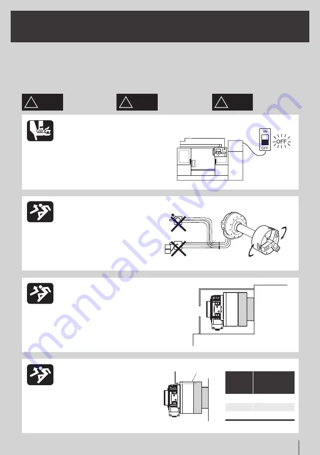
ON
OFF
NO!
7
Instruction Manual
사용 전에 알아두셔야 할 것, 지켜야 할
것을 정리해 놓았습니다. 반드시 읽어주
십시오. 당사는 이 취급설명서에 따르지
않은 경우에 발생하는 불량, 사고에 관한
책임은 지지 않습니다.
Please read this book before using
the chuck, and follow directions
given herein. We can not assume any
responsibility for any damage or ac-
cidents caused through things that is
not specified in this manual.
本守则记录了使用前应了解的事项,
请仔细阅读。
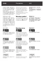
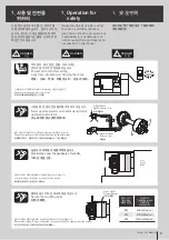
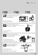
스핀들 회전 중에 전환밸브를 조작하시 마십시오.
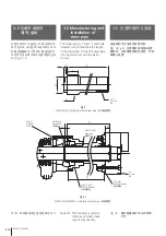
실린더의 외부에 커버를 부착하십시오.
볼트체결시 지정된 토크로 체결하십시오.
Power switch off before setting,
inspecting, lubricating or changing the chuck.
Never operate selector valve and solenoid valve
during spindle rotation.
Provide the cover the periphery of cylinder.
Secure the mounting bolts.
检查、加油、更换、附着夹头时,应关闭电源。
夹头旋转时禁止操作转换阔。
钳固定螺栓。
신체의 일부나 의복이 말려들어가 부상당하는 위험이 있습니다.
회전 중에 조작하면 파악된 공작물이 이탈(비산) 될 위험이 있습니다.
신체의 일부나 의복이 말려들어가 부상당하는 위험이 있습니다.
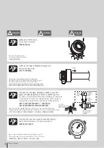
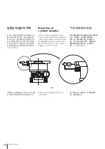
실린더 재질이 알루미늄이므로, 평상시 체결토크 보다 작게 해야합니다.
Danger by catching operator in a machine.
Danger by discharge of clamped workpiece during spindle rotation.
Loose clothing or limbs may be caught in the machine.
Because the cylinder is made of aluminum, torque specification is slightly lower than normal.
由于汽缸是由铝,拧紧扭矩应比常规的转矩小。
若身体或衣服被缠进去是十分危险。
若旋转时操作, 夹持的加工产品具有被甩出去(飞散)的危险。
气缸应该盖上盖。
醒目的运营商在一台机器上的危险。
척의 설치, 보수점검, 윤활, 수리 시에는
반드시 설치기계의 전원을 끄십시오.
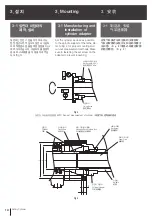
1. Operation for
safety
1. 安全守则
1. 사용 및 안전을
위하여
!
DANGER
위 험
!
DANGER
!
DANGER
危 险
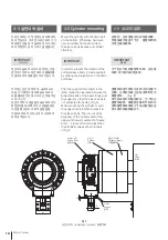
수동전환 밸브
솔레노이드 밸브
선반
실린더 아답터
Manual selector valve
Solenoid valve
Lathe
Cylinder Adaptor
手动转换阀
电磁阀
车床
气缸适配器
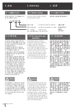
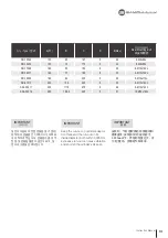
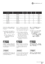
볼트 크기
Bolt size
纖检直径
체결 토크
Tightening torque
拧紧力矩
N·m(kgf·cm)
M10
60 N·m(6.1kgf·cm)
M12
87 N·m(8.9kgf·cm)
M16
205 N·m(20.9kgf·cm)
Summary of Contents for SD
Page 2: ......
Page 31: ...31 Instruction Manual n o t e...
Page 35: ...35 Instruction Manual n o t e...
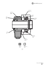
Page 38: ...21 26 19 20 23 25 18 17 22 16 15 24 38 Rotary Cylinder Fig 14...
Page 45: ......
Page 46: ......
Page 47: ......


