


25
Instruction Manual
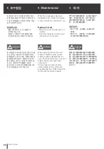
(1) 전원전압이 규정에 맞는지 확인하
십시오.
(2) 시운전시 압력조정 핸들을 최저압
의 상태로 놓고 미세조정(단,전원스
위치를 ON, OFF함)하여 펌프의 회전
방향을 확인하여 주십시오. 역회전하
고 있는 경우에는 전원 3선중 2선을
교환 연결해 주십시오. 회전방향 확
인 후 운전하여 주십시오.
(3) 척 작동압력은 먼저 최저압으로
낮춘후에 척 작동 가능한 저압력
(0.35~0.5Mpa)으로 설정하여 다음
사항을 확인하여 주십시오.
- 척 작동이 원활한가
- 작동방향은 정상인가
(척의 개폐방향)
- 작동 스트로크는 적정한가
(척의 죠 스트로크)
- 배관 각부의 누유 상태 는 양호한가
정상이면 작동압력을 서서히 높
이십시오.
상기 사항을 재확인한 후에 정격
압력까지 올려 주십시오. 그때 드레
인이 잘 되는지 확인하여 주십시오.
(4) 선반주축 회전수를 최저로 설정하여
회전시키십시오. 실린더 부착면,
지지대나 배관에 이상이 없으면 서서
히 회전 수를 높여 주십시오. 회전진
동이 과다 할때는 아답터의 면을 재
점검하여 주십시오.
(5) 유온이 낮을 시 (20~30℃이하)에
는 최고회전수의 1/3정도의 회전수
가 되게하여 운전하여 주십시오.
(1) Confirm the voltage is as specified.
(2) During the test run, set the pres
sure adjustment handle at the
minimum level and check the
direction of pump rotation by
inching (putting the switch on and
off briefly in alternation). If the
pump is rotating in reverse
direction, turn power source off.
Reverse two of three power wires.
After checking the direction of
rotation, run the cylinder.
(3) After lowering the chucking
pressure to the minimum pressure,
set the pressure to the lowest
setting at which the chuck may be
operated and check the following.
- Chuck operates smoothly
- Check that the chucking
direction is correct
(Clamp and unclamp)
- Chuck stroke is adequate
- Check for any leaks from hoses
After successfully checking for
all of the above, slowly raise the
operation pressure to the rated
pressure and recheck using
above guidelines. Check that the
drain flows smoothly.
(4) Rotate the lathe spindle at a
minimum revolution and slowly
raise the revolution unless there is
excessive run-out or problems with
the cylinder support. If there is
vibration, recheck the run-out of
the adaptor.
(5) If the oil temperature is low
(20~30℃), run the cylinder at 1/3
of its max rpm.
(1) 请检查电源电压是否符合规定。
(2) 进行调试时,请把压力调整把
柄放在最低压状态,进行细微调
整(把电源开关处于ON、OFF),
然后检查栗的旋 转方向。若发
现为逆旋转,请更换3根电
源线中的2根, 然后再连接,最
后确认旋转方向后再开始运转。
(3) 请把夹头启动压力降低到最低,
然后设定可启动夹头的低压
(0.35~0.5MPa),再检查如下
内容:
- 夹头的启动是否顺利。
- 启动方向是否正常
(夹头的开关方向)。
- 启动行程是否适当
(夹头的夹爪行程)
- 在各配管部位是否发生漏油
现象。
若以上内容均正常,请逐渐提高
启动压力。再次检查上述内容
后,请提高到额定压力。此时,
还应该检查排油 情况是否良
好。
(4) 请把车床主轴的旋转数设定成
最低,然后再使之旋转。若气缸
的安装部位、支架或配管没有异
常,请逐渐提高 旋转数。若旋
转震动过大,请检查适配器部
位。
(5) 若油温较低(20~30
℃
以下), 请
把旋转数设定为最高旋转数的
1/3左右, 然后再运转。
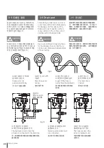
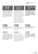
3-9 Trial operation
3-9 시운전
3-9 试运行
A sudden rise of cylinder temperature
(i.e.) from the machine operating
extended periods of time may cause
malfunction. When running, it is very
important to regularly clamp and
unclamp the piston.
실린더의 외주온도가 급격히 상승하는
경우,예를 들면 주축 풀리 등의 발열에
의해서 열영향을 받기도 하고, 실린더의
외주에 특별한 열발생원이 있을 때에 전
환 조작없이 장시간 연속운전 하면, 로크
기능을 내장하고 있는 실린더 봉입 압력
이 상승하여 실린더가 작동되지 않을때
가 있습니다. 특히 조정 운전시에는 이런
현상이 일어나기 쉬우므로 피스톤의 왕
복 동작을 빈번하게 하여 주십시오.
气缸外围温度急速上升的原因如下。
主轴滑轮发热时, 气缸外围产生特别
的热源时,此时。若不调整而长期 连
续运转。由于装有锁定功能的气缸密
封压力上升。有时气缸不启动。尤其
是。在调整运转时容易产生上述现
象。因此应经常进行活塞的往返动
作。
!
CAUTION
주 의
!
CAUTION
注 意
!
CAUTION
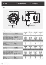
Summary of Contents for SD
Page 2: ......
Page 31: ...31 Instruction Manual n o t e...
Page 35: ...35 Instruction Manual n o t e...
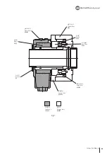
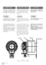
Page 38: ...21 26 19 20 23 25 18 17 22 16 15 24 38 Rotary Cylinder Fig 14...
Page 45: ......
Page 46: ......
Page 47: ......


