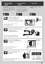
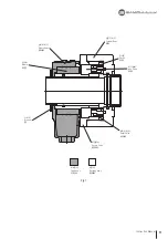
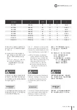
background image

a

d

b

f

e

c

16

Rotary Cylinder

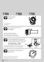
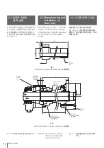
드레인 포트는 수직 방향이 되도록 부착
하여 주십시오. 구조상 드레인 포트가 수
직방향이 안될 경우 슬리브 바디의 양단
에서 작동유가 넘쳐 누유가 발생합니다.

Mount the cylinder with the drain port 
on the bottom. Otherwise, hydraulic 
oil will overflow from both ends of 
the sleeve body because of cylinder 
structure.

安装时。应以垂直方向安装排油雄。
若排油端不垂直于下方。套管体两结
会发生漏油现象。

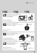
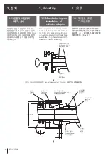
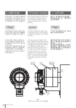
3-3 Cylinder mounting

3-3 실린더의 설치

3-3 油缸的装配

In order to prevent the rotation of the 
cylinder sleeve body, provide support 
by utilizing the projections on the drain 
port base.

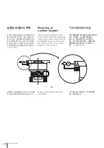
After the support is mounted to the 
lathe, retain the clearance between the 
projected parts of the sleeve body and 
the support so that the sleeve body is 
not subjected to loading. (Fig.5)
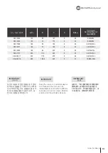
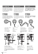
When mounting the cylinder, mount 
the support (anti-rotation bracket) to 
the sleeve body. The run-out of the 
periphery of the cylinder and of the 
upper and lower movement of sleeve 
body’ s rear end must be less than
the standard values shown in table 
of Fig.6.

실린더의 슬리브 바디가 회전하는 것을 
방지하기 위해 드레인 포트의 돌출부를 
이용하여 지지대를 설치하여 주십시오.

지지대는 선반에 부착 후, 슬리브 바디
에 힘이 가해지지 않도록 슬리브 바디
의 돌출부와 지지대 사이에 간격을 주십
시오. (Fig.5)
실린더 부착 시 흔들림은 슬리브 바디의 
회전방지를 하도록 하고 스핀들을 회전
시켰을 때 실린더의 외주 흔들림을
그림6과 표에 표시한 규격치 이하로 부
착하여 주십시오.

为了防止气缸的套管体回转。应在排
油的 突出部位安装支架。

套管体的突出部位与支架之间应留下
间隔。以便在车床上安装支架时压不
蕃套管体 。(Fig.5)
就气缸安装时的摇动而言。为了防止
套管体旋转。使旋转主轴时气缸的外
围和套管体后端的上下摇动程度应在 
图 6表示的规格值以下。

IMPORTANT

유의사항

IMPORTANT

重 要

IMPORTANT

Fig.5

실린더 부착 / Installing of cylinder / 

安装气缸

실린더 아답터

실린더

슬리브 바디

선반

지지대

Cylinder Adaptor

Cylinder

Sleeve Body

Lathe

Support

气缸适配器

气缸

袖长体

车床

支持

Summary of Contents for SD

Page 1: ...raulic Cylinder Instruction Manual SD SDL IMPORTANT Please read and understand DANGER WARNING items in this maunal before operating the cylinder Please keep this manual by your side for answers to any...

Page 2: ......

Page 3: ...asizes important information Warning symbol Warning term DANGER WARNING CAUTION IMPORTANT Indicates an imminently hazardous situation which if not avoided will result in death or serious injury These...

Page 4: ...4 Rotary Cylinder 1 7 2 10 2 1 10 2 2 10 3 12 3 1 12 3 2 14 3 3 16 3 4 19 3 5 20 3 6 21 3 7 23 3 8 24 3 9 25 3 10 27 4 28 5 29 6 32 7 36 8 40 8 1 40 8 2 41 8 3 42 8 4 43...

Page 5: ...3 3 Cylinder mounting 16 3 4 Torque spec for cylinder mounting bolts 19 3 5 Drain port 20 3 6 Oil Pressure circuit diagram 21 3 7 Setting up the control valve hydraulic unit and piping 23 3 8 Hydrauli...

Page 6: ...6 Rotary Cylinder 1 7 2 10 2 1 10 2 2 10 3 12 3 1 12 3 2 14 3 3 16 3 4 19 3 5 20 3 6 21 3 7 23 3 8 24 3 9 25 3 10 27 4 28 5 29 6 32 7 35 8 39 8 1 39 8 2 40 8 3 41 8 4 42...

Page 7: ...e during spindle rotation Provide the cover the periphery of cylinder Secure the mounting bolts Danger by catching operator in a machine Danger by discharge of clamped workpiece during spindle rotatio...

Page 8: ...Gripped workpiece may discharge by lighting or interruption Set work to correct gripping position o Install the cylinder with the piston in its forward position Danger by discharge of clamped workpiec...

Page 9: ...use loss of force which may cause in the workpiece to be thrown from the chuck Improper lifting can lead to damage or injury Debris in the oil may result in pressure loss and cause the workpiece to be...

Page 10: ...nt thermal expansion off SD SD SDL Standard type Long stroke type SD 135 46 Nominal Through Hole Diameter Nominal inner diameter of cylinder 2 2 Summary 2 2 1 Model coding 2 1 2 2 Construction and ope...

Page 11: ...11 Instruction Manual Fig 1 Sleeve Body Sleeve Stopper Rotary Valve Fixed ass y Rotating ass y Relief Valve lock Valve Piston Cylinder Body...

Page 12: ...asurement methods Make sure to fastening the set screw on the adapter to prevent loosening Fig 2 Fig 3 Fig 2 Fig 3 Fig 2 Fig 3 Run out measurement of cylinder 3 Mounting 3 3 3 1 Manufacturing and inst...

Page 13: ...6 M10x100L SD 18582 160 82 205 5 25 6 M10x110L SD 21510 200 103 240 5 35 6 M12x120L SDL 25411 230 117 5 275 6 46 8 M12x140L SDL 30516 260 166 5 345 5 51 12 M12x160L Keep the run out on cylinder adapto...

Page 14: ...draw pipe into the piston rod with the piston rod set Note B The following is cylinder dimensions when chuck jaws is fully opened Fig 4 4 1 B Fig 4 A B 3 2 Manufacturing and installation of draw pipe...

Page 15: ...daptor and back plate is 800mm in case of HS 06 and SD 13546 the overall length of the draw pipe will be as follows L A 41 800 41 841mm Accurate threading must be provided on the draw pipe in conformi...

Page 16: ...support is mounted to the lathe retain the clearance between the projected parts of the sleeve body and the support so that the sleeve body is not subjected to loading Fig 5 When mounting the cylinder...

Page 17: ...face should be minimized 0 005 less 0 005 0 005 Fig 6 Run out cylinder after installation Type A B SD 13546 SD 13546 equivalent SD 13546 0 01 Less 0 015 SD 15452 SD 15452 equivalent SD 15452 0 01 Less...

Page 18: ...ylinder please follow the example as shown below Attach a tester such as a JURACON gauge to a Vblock and test the OD run out on the cylinder adaptor 0 010 or less Make sure the gauge touches the cylin...

Page 19: ...0 20 SD 15452 M10 20 SD 17568 M10 20 SD 18577 M10 20 SD 18582 M10 20 SD 21510 M12 20 SDL 25411 M12 32 SDL 30516 M16 32 2 Tab Depth Screwing Length Mounting Bolt Cylinder Adaptor Cylinder Tighten the m...

Page 20: ...wire reinforced clear vinyl hose for the drainage hose so that the oil can be seen Below are bad examples of hose routing Drain port is not positioned vertically The hydraulic circuit of another actu...

Page 21: ...it is incorporating the locking mechanism which works to retain the specified gripping force even when abnormal drop of the supplied pressure is caused by power failure or breakdown of pressure source...

Page 22: ...r dia outer dia gripping change valve so that it prevents misoperation when changing from the inner dia gripping to outer dia gripping When the solenoid valve is used for this change valve use the 4 p...

Page 23: ...the pipe and then install it Dusts in the pipe can be a cause of cylinder overheat 3 7 Setting up the control valve hydraulic unit and piping 3 7 3 7 Remove any dirt completely from inside of the Pip...

Page 24: ...oil is influenced to the cylinder heating drain volume opera tion speed regulate the oil according to the instruction manual of the pump unit 20 20 IMPORTANT IMPORTANT IMPORTANT 40 30 50 cSt ISO VG32...

Page 25: ...ng direction is correct Clamp and unclamp Chuck stroke is adequate Check for any leaks from hoses After successfully checking for all of the above slowly raise the operation pressure to the rated pres...

Page 26: ...rox 0 5Mpa each and repeat the same procedures as described in above 2 for confirmation of cylinder motion At this time increase the pressure to 30 of maximum chuck pressure When cylinder operational...

Page 27: ...perature rapidly deteriorating the sealing materials and the hydraulic oil Keep the oil temperature below 60 by use of a cooler In this case minimize the back pressure 60 3 10 Safety valve 3 10 3 10 A...

Page 28: ...heck the hydraulic oil twice a year and replace it if necessary 0 2 3 6 When operating the machine with maximum hydraulic pressure and maximum speed disassemble it at every 250 thousands times of use...

Page 29: ...ce to rotation Copper tube piping materials are used Use the proper hose material hydraulic rubber hose Part of the sleeve body is fixed to the lathe There must be some space between the housing and a...

Page 30: ...d head radiation insufficient Remove part of lathe cover of provide air vent Coolant leaks from coolant collector or mixes into hydraulic oil Coolant collector filter loaded with chips Clean filter Pi...

Page 31: ...31 Instruction Manual n o t e...

Page 32: ...essure 4 5 45 4 5 45 4 5 45 4 5 45 min 1 Max r p m 7000 6200 5600 5000 N m2 kg m2 GD2 0 021 0 045 0 07 0 097 kg Weight 10 14 18 23 Leak min Total Leakage 3 3 5 4 4 5 SD 18582 SD 21510 SDL 25411 SDL 30...

Page 33: ...5 0 4 0 Wmax 55 50 59 56 53 60 75 76 Wmin 30 25 30 27 23 25 25 25 Z 5 5 5 8 5 5 6 5 A1 8 5 8 5 11 11 11 14 18 17 5 B1 117 5 107 5 122 5 129 5 133 140 178 5 206 C1 30 30 30 35 35 30 45 45 E1 M6 M6 M6...

Page 34: ...n Thrust kN x Hydraulic Pneumatic Pressure MPa 0 25 MPa Max Hydraulic Pneumatic Pressure MPa 0 25 MPa Note3 The locking mechanism Temporarily maintains the hydraulic pressure in the cylinder if the pu...

Page 35: ...35 Instruction Manual n o t e...

Page 36: ...1 2 5 11 24 15 16 17 10 18 19 25 22 3 4 6 7 26 27 32 30 12 29 28 13 20 14 21 23 8 9 31 36 Rotary Cylinder 7 Parts list 7 7 Fig 13...

Page 37: ...Regard 1 11 Regard 1 12 Splash Plate 1 13 Bearing 2 14 Wrench Bolt 6 15 O Ring O 1 16 O Ring O 1 No Name Q ty 17 O Ring O 1 18 O Ring O 1 19 O Ring O 1 20 O Ring O 3 21 O Ring O 1 22 O Ring O 2 23 O R...

Page 38: ...21 26 19 20 23 25 18 17 22 16 15 24 38 Rotary Cylinder Fig 14...

Page 39: ...290 1 18 AS5685 250 AS568 257 AS568 259 AS568 262 AS568 262 AS568 267 G240 AS568 380 1 19 P53 P60 P75 P85 P90 P120 P125 P175 1 20 S105 S105 G125 G135 G145 AS568 262 G190 G250 3 21 S70 S80 S95 S105 S11...

Page 40: ...SD 13CS CS13SHW UN CS13SH SD 13546 SD 15CS CS15SHW UN CS15SH SD 15452 SD 16CS SD 17568 SD 17CS CS18SHW UN CS18SH SD 18577 SD 18CS CS19SHW UN CS19SH SD 18582 SD 21CS CS21SSHW UN CS21SH SD 21510 SD 25C...

Page 41: ...Specification PR12 2DP AUTONIX OP2 WHITE V RED OV BLACK OP1 WHITE 1mm LED The proximity switch is mounted to brackets through the adjusting plate and must be set with the screws of the proximity swit...

Page 42: ...ommended to use transparent vinyl hose for checking flow condition inside dia 32mm Fig 16 32mm Fig 16 32mm Fig 16 CAUTION CAUTION CAUTION Fig 16 15 If coolant flows over from the coolant collector it...

Page 43: ...Name Q ty 1 Body 1 2 Cover 1 3 Sheet packing 1 4 Detectable Plate 1 5 Sheet packing 1 6 Plate 2 7 Sheet packing 2 8 O Ring O 2 No Name Q ty 9 Filter 1 10 Under body 1 11 Hexagon Socket Head Bolt 9 12...

Page 44: ...er 1 5 Sheet packing 1 6 Detectable Plate 1 7 Plate 2 8 Sheet packing 2 9 Filter 1 No Name Q ty 10 Under body 1 11 Hose nipple 1 12 Hexagon Socket Head Bolt 3 13 Hexagon Socket Head Bolt 4 14 Hexagon...

Page 45: ......

Page 46: ......

Page 47: ......

Page 48: ...rea P ro d u c tio n m o n ito re d T yp e te st e d P ro d u kt io n u b er w ac h t B au ar t g ep ru ft s ISO 9001 2008 Samchully Machinery 405 820 99 TEL 82 32 822 4811 FAX 82 32 822 4377 405 820...

Reviews: