

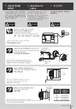


경고 용어
안전하게 사용하기 위해서 필요한 경고
사항을 본서에 기재했으니, 반드시 읽어
주십시오. 문장 중의 마크는 특히
주의하여 주십시오. 산업용 기계이므로
사용자 또는 이 장비를 사용하는 다른 사
람에게 위험할 수 있는 항목이나 조작에
는 “안전 경고 기호” 를 사용하여 사용
자의 주의를 환기시킵니다. 안전 경고 기
호로 표시한 지침을 잘 읽고 반드시 준수
해 주십시오.
안전 경고 기호
삼천리기계의 제품을 사용해 주셔서 진
심으로 감사 드립니다. 본 취급설명서에
따라 제품의 사용방법을 바르게 이해하
시고, 귀사의 생산에 기여할 수 있도록
활용하여 주십시오.
또한, 알아두면 편리한 제품의 성능 등에
관하여 유의사항으로 설명해 두었습니
다. 본 취급설명서는 분실되지 않도록 항
상 제품 가까이에 보관하여 주십시오.
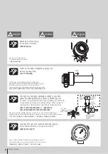
!
!
DANGER
위 험
적절한 안전 절차와 지침을 준수하지 않
으면 사망에 이르거나 중상을 입게 되는
매우 위험한 상황을 나타냅니다.
!
WARNING
경 고
적절한 안전 절차와 지침을 준수하지 않
으면 사망에 이르거나 중상을 입을 수
있는 잠재적으로 위험한 상황을 나타
냅니다.
!
CAUTION
주 의
적절한 안전 절차와 지침을 준수하지 않
으면 가벼운 상처나 부상을 입을 가능성
이 있는 잠재적으로 위험한 상황을 나
타냅니다.
IMPORTANT
유의사항
제품의 성능 및 오류나 실수를 막기 위
한 지침입니다.
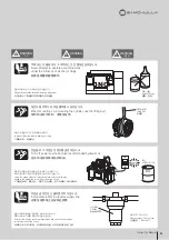
Precautions
前言
머리말
警告事项
!
DANGER
危 险
!
WARNING
警 告
!
CAUTION
注 意
IMPORTANT
重 要
具有跟重大的事故和死亡差不多的
危险。
可能引起轻微的负伤或产品受损。
容易疏失的事项以及应该熟悉的产
品性能。
真诚感谢您购买我们三千里公司的
液压卡盘。
请正确地理解本液压卡盘的操作说明
书中明示的使用方法,以便提高贵司
的生产能力。
警告标志
为了用户的安全,本说明书记载了必
要的“警告事项”,请您务必阅览。
说明书中标明要 特别注意。关于液
压卡盘的性能等,我们用”留意事
项”进行了说明。
可能引起重大事故和死亡的危险。
Thank you so much for choosing
Samchully. Please read this manual
carefully and fully understand the
procedures for installation, operation,
inspection and maintenance before
operating the product.
Keep this manual handy as it contains
detailed information on product
functionality.
To ensure safe operation, please read
this instruction manual and pay partic-
ular attention to the symbol which
emphasizes important information.
Warning symbol
Warning term
!
DANGER
!
WARNING
!
CAUTION
IMPORTANT
Indicates an imminently hazardous
situation which, if not avoided, will
result in death or serious injury. These
warning messages include the preven-
tive actions that are indispensable to
avoiding danger.
Indicates a potentially hazardous
situation which, if not avoided, will
result in death or serious injury. These
warning messages include the preven-
tive actions that are indispensable to
avoiding danger.
Indicates a potentially hazardous
situation which, if not avoided, could
result in minor injury or machine
damage.
Instructions for optimal performance
and avoiding errors or mistakes.
!
Summary of Contents for SD
Page 2: ......
Page 31: ...31 Instruction Manual n o t e...
Page 35: ...35 Instruction Manual n o t e...
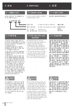
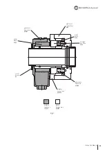
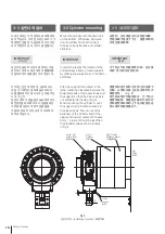
Page 38: ...21 26 19 20 23 25 18 17 22 16 15 24 38 Rotary Cylinder Fig 14...
Page 45: ......
Page 46: ......
Page 47: ......


