


15
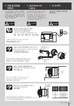
Instruction Manual
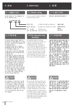
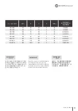
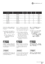
형식
/ Type
a
b(f7)
c
d
L
SD-13546
M52x2.0p
48
25
5
A+B+8
SD-15452
M60x2.0p
55
30
12
A+B+20
SD-17568
M75x2.0p
72.5
25
5
A+B+5
SD-18577
M85x2.0p
82
25
5
A+B+5
SD-18582
M90x2.0p
85
35
12
A+B+20
SD-21510
M112x2.0p
106
30
12
A+B+9
SDL-25411
M130x2.0p
123
45
15
A+B+15
SDL-30516
M180x3.0p
170
45
15
A+B+12
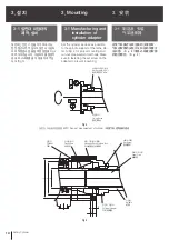
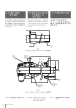
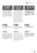
The “L” dimension can be found by
the above table when the distance A
between the cylinder adaptor and the
chuck mounting face is given.(Fig.4-1)
ex) When the distance A (between
cylinder adaptor and back plate)
is 800mm in case of HS-06 and
SD-13546 the overall length of the
draw pipe will be as follows.
L=A+41= 800 + 41 = 841mm
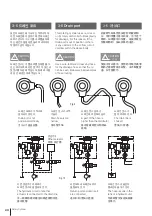
● Accurate threading must be
provided on the draw pipe in
conformity.
표에서 L치수는 실린더 아답터와 척 아
답터 간의 거리 A가 정해지면 결정됩니
다. (Fig.4-1)
예) HS-06과 SD-13546에 실린더 아
답터, 척아답터 사이의 거리 A=800
일 경우, 드로우파이프의 전체 길
이는
L = A + 41 = 800 + 41 = 841mm
● a 나사는 피스톤 로드의 나사
에 맞도록 정확히 나사가공을
해 주십시오.
表中 L 尺寸可确定油缸 Adapter
与卡盘 Adapter 之间的距离
A。(Fig.4-1)
例)假定HS-06, SD-13546 组合成
A=800,拉制管的全长L是
L=A+41=800+41=841
●
a部分螺丝加工,应对准油
缸 Pitch 螺丝部分正确加
工.(Fig.2)如果螺丝
接触松,会发生振动。
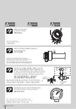
Make sure the draw pipe hardness is
adequate. Damage to draw pipe due
to insufficient hardness will risk the
workpiece being thrown from the
chuck.
드로우파이프는 충분한 강도를 갖도록
해주십시오. 강도부족시 파손되면 일순
간에 파악력이 떨어져 공작물 이탈(비산)
의 위험이 있습니다.
拉管应具有足够的强度. 若强度不
足。 则夹持力不足。夹头有可能被
用出去(飞敗)的危险。
!
WARNING
경 고
!
WARNING
警 告
!
WARNING
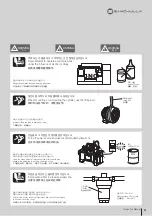
Loosening of threads during operation
can cause vibration and weaken the
draw pipe. Thread D, F should be
concentric whithin 0.05mm T.I.R.
나사의 체결이 풀어지면 진동 또는 강도
부족의 원인이 됩니다. D, F의 동심도는
0.05mm이하로 해주십시오.
若丝松开. 会产生震动或使强度下
降。a和e的同心度应小于0.05mm。
IMPORTANT
유의사항
IMPORTANT
重 要
IMPORTANT
Summary of Contents for SD
Page 2: ......
Page 31: ...31 Instruction Manual n o t e...
Page 35: ...35 Instruction Manual n o t e...
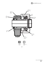
Page 38: ...21 26 19 20 23 25 18 17 22 16 15 24 38 Rotary Cylinder Fig 14...
Page 45: ......
Page 46: ......
Page 47: ......


