


28
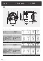
Rotary Cylinder
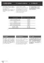
4. Maintenance
4. 维修
4. 보수점검
실린더에 누유가 있다면 분해청소 하고
오링 등을 교환하여 주십시오. 분해 청소
시 일부 경합금을 사용하였으므로, 취급
에 주의하여주십시오.
유압유니트
- 흡입 스트레이너는 2~3개월마다
세척해 주십시오.
- 작동유는 6개월 주기로 열화상태를
점검하여 필요시 교환하여 주십시오.
When the oil leakage is observed,
disassemble the cylinder and replace
o-rings. Handle the cylinder with care.
Hydraulic Unit.
- Clean the suction strainer every 2~3
months.
- Check the hydraulic oil twice a year
and replace it if necessary.
若气缸出现漏油现象, 应拆开后进行
清扫, 更换0型环等。由于气缸的一
部分使用轻合金制成,在拆开清扫
时, 应注意谨慎操作。
液压组件
- 每2~3个月, 应清洗一次吸入粗
滤器。
- 每6个月 , 应检查一次启动油的
劣化状态并更换启动油。
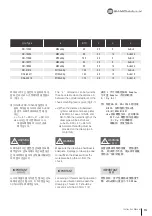
When operating the machine with
maximum hydraulic pressure and
maximum speed, disassemble it at
every 250 thousands times of use and
replace the seal and check each
component.
Using a large unit risks pressure
spikes (surges) in the system and
may damgage the cylinder. Adjust the
throttle valve to reduce pressure.
최고유압력과 최고회전수에 가깝게 사용
하는 경우는 사용회수 25만회정도에서
분해점검하고, 씰의 교환, 부품의 세밀한
점검등을 해주십시오. 대형유압 유니트
를 사용하는 경우는 과다한 써지압이 일
어나서, 실린더의 작동불량, 파손의
원인이 될 수 있으므로 교축밸브를 이용
하여 써지압을 낮추어 주십시오.
若接近于使用最高液压和最高旋转
数,应在使用25万次左右后拆开检
查,并应更换密封材以及详细检查配
件。使用大型液压组件时,有时因过
大的冲击压力,使气缸不动作或使气
缸损坏,因此应使用节流闽降低冲
击 压力。
!
WARNING
경 고
!
WARNING
警 告
!
WARNING
Summary of Contents for SD
Page 2: ......
Page 31: ...31 Instruction Manual n o t e...
Page 35: ...35 Instruction Manual n o t e...
Page 38: ...21 26 19 20 23 25 18 17 22 16 15 24 38 Rotary Cylinder Fig 14...
Page 45: ......
Page 46: ......
Page 47: ......


