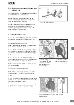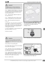
9.2.7 Caulk the bushing (7) against longitudinal
shift in the brake calliper. To this end, screw in the
hex screw (arrow B) of the embossed part (T16) as
far as it will go (see Fig.).
9.2.8 Screw back the hex screw (arrow B) of the
embossed part (T16) approx. 20 mm, loosen the
brass nut (T14) and turn the embossed part (T16)
approx. 60°. Repeat the caulking process. See
Fig. 9.2.7.
The bushing (7) is now caulked with the groove of
the brake calliper (arrow A).
9.2.9 Screw the spindle (T13) out of the em-
bossed part (T16) and remove the tool combination.
9.2.10 Check the seating of the bushing (7) for
burr formation and remove any burrs if necessary.
Smear the bushing (7) with white grease (supplied
in the repair kit).
9.3 Replacing the slide bearing (6) on
the short bearing side
In order to simplify the composition of tools and
components, they are allocated item numbers (see
Chap. 2.1).
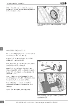
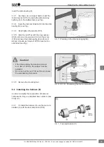
9.3.1 To replace the slide bearing (6), use the tool
combination (5) (see Fig.).
Pulling out the slide bearing (6)
9.3.2 Remove the guide bushing (4)
9.3.3 Clean the bearing in the pad shaft area.
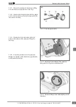
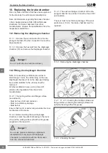
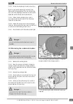
9.3.4 Position the tool combination (S) as shown
(see Fig.).
9.3.5 Hand tighten the nut (T14).
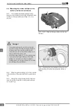
9.3.6 Hold the nut (T14) with the ring spanner
AF24 and use a suitable tool (e.g. ratchet wrench
AF24) to turn the screws on T20 and pull out the
slide bearing (6) (see Fig.).
9.2.7 - 9.2.8 - Caulking the bushing against
longitudinal shift
9.3.1 - Tool combinations (S)
9.3.4 - 9.3.6 - Pulling out the slide bearing
Repairing the brake calliper bearing
42
en
XL-SA40001RM-en-DE Rev A • 02.2016 • Errors and changes excluded © SAF-HOLLAND


