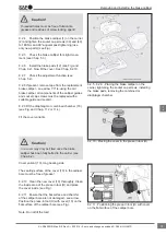
The inner bellows (9) must be compressed
(see Fig.) as otherwise the movement of the
brake calliper will be restricted.
Caution!
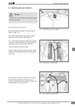
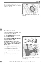
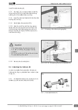
8.2.12 Using your hand, press the mandrel of
the press-in tool (H) as far as it will go. Then use
a hammer to drive it in as far as it will go (see
Fig. 8.2.12).
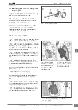
Note: After fitting the new cover (10), a 2 mm
protrusion of the cover (10) with respect to the flat
surface must be ensured (see Fig.).
Cover (68), short bearing side
The seating surface of the cover (68) in the calliper
bore must be free of grease!
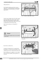
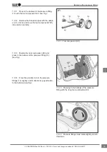
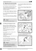
8.2.13 Clean the new cover (68) thoroughly. Clean
the inside area of the press-in tool (M) and place
the cover inside (see Fig.).
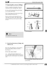
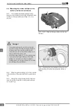
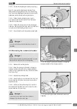
8.2.14
Ensure that the flat surface and chamfer
of the calliper bore are not damaged - see arrow.
Position the press-in tool (M) with cover (68) on the
flat surface of the calliper bore (see Fig.).
Note: Do not tilt the tool!
The inner bellows (9) must compressed as
otherwise the movement of the brake calliper will
be restricted.
Caution!
8.2.12 - Driving the press-in tool (H) with a hammer
as far as it will go
8.2.13 - Placing the cover in the press-in tool (M)
8.2.14 - Positioning the press-in tool (M) with cover
on the flat surface of the calliper bore
Removing and installing the brake calliper
38
en
XL-SA40001RM-en-DE Rev A • 02.2016 • Errors and changes excluded © SAF-HOLLAND


