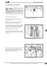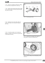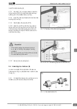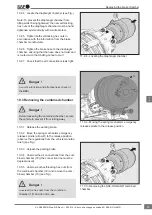
8.2.15 Using your hand, press the mandrel of the
press-in tool (M) as far as it will go. Then use a
hammer to drive it in as far as it will go (see Fig.).
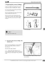
Note: After fitting the new cover (68), a 15.5 mm
protrusion of the cover (68) with respect to the flat
surface must be ensured (see Fig.).
Fitting the cover with the brake calliper (1) and
carrier (2) removed:
8.2.16 Check the brake calliper for slight move-
ment (see Chap. 5.3).
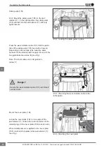
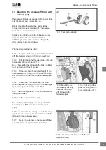
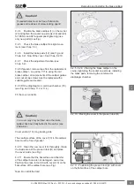
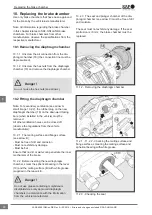
8.2.17 In the clamping position shown (e.g. vice),
press the carrier (2) as far as possible against the
brake calliper (1).
The inner bellows (9) must be compressed
(see Fig.) as otherwise the movement of the
brake calliper will be restricted.
Danger !
8.2.18
The cover (10) or (68) can only be fitted as
described above (see Chap. 8.2.10 to 8.2.15).
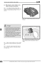
8.2.19 Mount the carrier complete with brake cal-
liper to the axle (use only new screws, observe the
prescribed tightening torques).
Note: When mounting to the vehicle axle,
the regulations from the respective vehicle
manufacturer must be observed.
8.2.20 Install the brake pads (see Chap. 6.2).
8.2.21 Check the adjustment function (see
Chap. 5.2).
8.2.22 Fit the diaphragm or combined chamber
(see Chap. 11.2 or 11.4). Then adjust the clear-
ance. See Chap. 5.2.6.7.
8.2.23 Fit the wheels (observe the information
from the axle/vehicle manufacturer)
After completing work on the disc brake, always
perform a final check on the roller test bench to
verify function and effectiveness. Note that the
brake pads and/or brake disc may have reduced
braking efficiency during their run-in phase.
Danger !
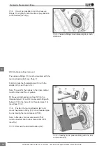
8.2.15 - Driving the press-in tool (M) with a hammer
as far as it will go
8.2.17 - Pressing the carrier (2) against the brake
calliper (1)
Removing and installing the brake calliper
39
en
XL-SA40001RM-en-DE Rev A • 02.2016 • Errors and changes excluded © SAF-HOLLAND

