Threaded holes must be free of lubricants,
grease and residues of screw locking agent!
Caution!
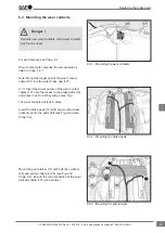
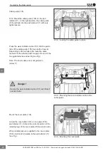
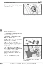
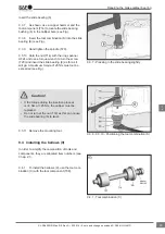
8.2.4 Position the brake calliper (1) on the carrier
(2) and tighten the socket cap screws (39) and (40)
to 180 Nm and 90° angular post-tightening (use
only new parts) (see Fig.).
8.2.5 Check the brake calliper for slight move-
ment (see Chap. 5.3).
8.2.6 Install the brake pads (12) (see Fig. and
Chap. 6.2). Now fit the cover. See Chap. 8.2.10.
8.2.7 Check the adjustment function (see
Chap. 5.2).
8.2.8 If present, remove tape from the replacement
brake calliper - see arrow Y. If re-using the old
brake calliper, all components of the calliper guides
and socket cap screws must be replaced with a
suitable guide and seal kit.
8.2.9 Fit the diaphragm or combined chamber (18)
(see Fig. and Chap. 11.2 or 11.4).
Fit the cover variants
The cover may only be fitted once the brake
calliper has been fully bolted to the carrier (see
Chap. 8.2).
Caution!
Cover variant (10), long bearing side
The seating surface of the cover (10) in the calliper
bore must be free of grease!
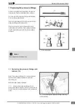
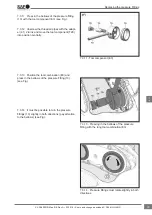
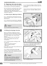
8.2.10 Clean the new cover (10) thoroughly. Clean
the inside area of the press-in tool (H) and place
the cover inside (see Fig.).
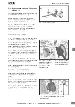
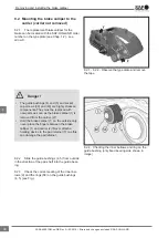
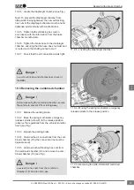
8.2.11
Ensure that the flat surface and chamfer
of the calliper bore are not damaged - see arrow.
Position the press-in tool (H) with cover (10) on the
flat surface of the calliper bore (see Fig.).
Note: Do not tilt the tool!
8.2.5 - 8.2.9 - Placing the brake calliper on the
carrier, tightening the socket cap screws, installing
the brake pads, removing the combined or
diaphragm chamber
8.2.10 - Placing the cover in the press-in tool (H)
8.2.11 - Positioning the press-in tool (H) with cover
on the flat surface of the calliper bore
Removing and installing the brake calliper
37
en
XL-SA40001RM-en-DE Rev A • 02.2016 • Errors and changes excluded © SAF-HOLLAND


