23
Keep the manual for future reference - For more informations visit www.saerelettropompe.com
The connection to the power grid must be done in the respect of the local and national standards of the electric system of the place
where the pump is installed.
5.2 PLACE OF INSTALLATION (Fig.9)
WARNING!
Prepare a concrete base for the complete set, and raise it, up to the required height (minimum 300 mm).
Make sure that the pump’s support surface is solid and even (so that it rests on all the feet) and that the load capacity of the surface
is adequate for the weight shown on the plate.
Verify that the surrounding area is sufficient for ventilation and allows movement in the case of maintenance.
Select suitables point and area of fixing: verify the prevention of possible vibrations to the surrounding structures.
Check that the strength of the concrete foundations is appropriate and complies with current relevant regulations.
It is recommended for the foundation base, a weight about five times major then the weight of the complete set.
The pump/electric pump must be installed as close as possible to the suction point of the liquid.
The available NPSH value in the lifting plant must be always bigger than the pump’s NPSH , both in installation under head and over
head in order to avoid cavitation.
As far as hot liquids are concerned, NPSH must be re-calculated, in order to obtain the required head in any case.
If you pump toxic or harmful liquids or at high temperatures, it is important to taken all necessary precautions to avoid any loss
and/or leakage that could cause damage to persons, animals, property or to he environment.
5.3 BASEMENT FIXING TO THE GROUND (Fig.7)
i. Insert the anchor bolts into the appropriate basement holes and into the basic foundation.
ii. To position the complete set, at the required height, insert the shims, under the basement, and closed to the anchor bolts, in an intermediate positions.
If the basement is provided with threaded holes, use a screw instead of the shim for the leveling.
iii. Perform a first alignment between pump and motor.
iv. Fix the anchor bolts with the proper product (pourable mortar for anchors)
v. When bolts are anchored, proceed to a first tightening of the screw nuts bolts.
vi. Recheck the alignments between complete set and pipes and between pump and motor, then, if necessary, make the correction needs.
vii. Use the anchor mortar to “drown” the base. This, together with the basic foundation, will build a very rigid base for the pump. Moreover, if necessary,
before to drip the mortar, build a mortar containment basin around the basement.
CONNECTING THE PIPES (Fig.9)
WARNING!
The pump maximum working pressure can’t be bigger than the PN pump nominal pressure.
Pipes must be suitable for the pump maximum working pressure.
WARNING!
The intake and delivery pipes must not transmit forces to the pumps/ electric pump due to their own weight and/or heat expansion, at
the risk of possible liquid leaks or breaking the pump. For this reason, the pipes must be supported by anchorages and, if necessary,
expansion joints must be inserted in the appropriate positions.
Refer to
TAB.II
for permissible forces and moments at pump nozzles.
Pumps don’t have to transmit vibrations to the pipes, therefore insert anti-vibration couplings in delivery and, if it is possible, in
suction.
WARNING!
Install non return valve on the discharge side.
Install gate valve both in suction and discharge side.
The intake pipe must always be perfectly air tight and not positioned horizontally, but must always rise towards the pump. On the other hand, in the case of
operation under water head, the intake pipe must always slope down towards the pump. For this reason, any fitting cones 1 must be eccentric and oriented
to avoid the formation of bubbles during priming or operation.
It is a good idea to protect the pump by inserting a filter on the intake pipe; especially during the initial period of operation, the pipes release slags capable
of damaging the pump seals. The filter must have a mesh less than 2 mm and a free passage area of at least 3 times the section area of the pipe so as
to avoid excessive losses of head.
To adjust the flow rate, it is a good idea to install a shutter on the delivery pipe.
The diameter of the pipe must be such that the speed of the liquid never exceeds 1,5 - 2 m/s at intake and 3 – 3,5 m/s at the delivery. In any case, the
diameter of the pipe must not be less than the diameter of the pump openings.
The suction piping must be absolutely hermetic and for the catalogue data
it must have the diameters of
TAB.III
(pipes of smaller diameters reduce the delivery values).
After having performed the controls listed, connect the pipelines to the pump.
ALIGNEMENT
WARNING!
Although the group has already been fully aligned before shipment, it is necessary to check and recalibrate the alignment after having
installed the complete set.
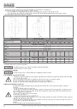
- Remove the coupling guard.
- Check the axial alignment, it must be within the limits (S1max / S1min).
- Check the angular alignment through a feeler gauge: the angular displacement has to be measured as the difference of the gap between the two half
coupling (Smax - Smin)
Summary of Contents for NCB
Page 60: ...60 1 1 2 2 IEC 60364 4 3 www saerelettropompe com...
Page 62: ...62 SAER EN809 5 5 SAER 40 C 40 C 1000 www saerelettropompe com...
Page 65: ...65 6 9a i ii iii 6 iv v vi 9b i ii 6 iii iv v 1 2 3 40 C 90 C 50 C PN www saerelettropompe com...
Page 66: ...66 30 20 100 10 7 o o 1500 o o www saerelettropompe com...
Page 73: ...73...
Page 75: ...75...


