background image

Zeus III

Party Line Introduction and Operation  47

Bosch Security Systems, Inc.

Technical Manual

 F.01U.193.289

Rev. 05

5.

Click 

Set Input Gain

 when you are finished.

The input is adjusted

.

Call Signalling

Zeus III party line channels (CH1 and CH2, see Figure 3 on page 13) support an integrated call signalling function controlled 
through the use of UPL statements in AZedit. Using a UPL statement, you can configure an indicator to activate when calls are 
received.

NOTE:

Call signalling support is only available with AZedit version 3.6.4 and later.

To

 configure incoming call signalling from a 2-wire system

, do the following:

1.

In AZedit, from the System menu, select 

UPL Statements

.

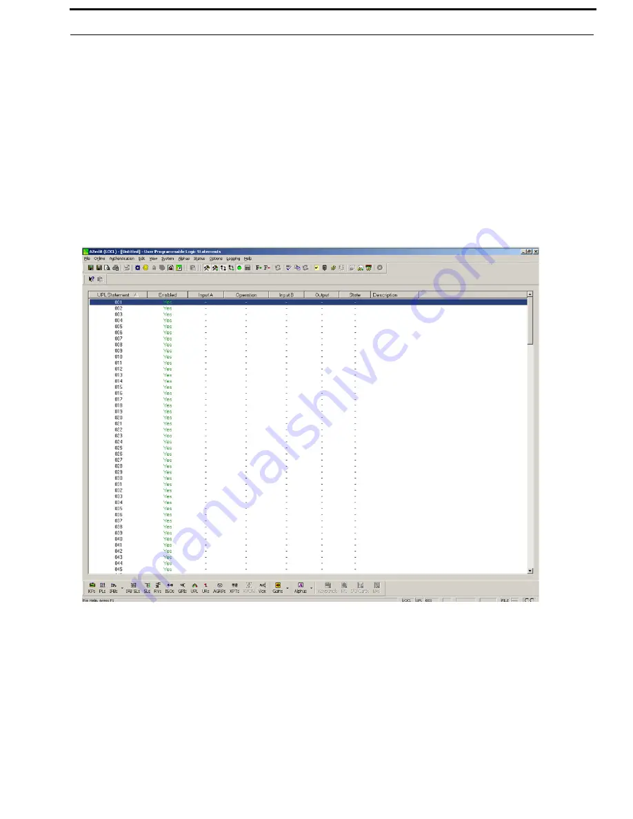
The User Programmable Logic Statements window appears

.

FIGURE 40.

User Programmable Statements Window – AZedit

Summary of Contents for Zeus III

Page 1: ...F 01U 193 289 Rev 05 OCTOBER 2015 Zeus III Matrix Intercom User Manual Up to and including version 1 0 0...

Page 2: ...or implied warranty with respect to anything contained in this manual and shall not be held liable for any implied warranties of fitness for a particular application or for any indirect special or con...

Page 3: ...If the provided plug does not fit into your outlet consult an electrician for replacement of the obsolete outlet 10 Protect the power cord from being walked on or pinched particularly at plugs conven...

Page 4: ...Bosch Security Systems Inc Technical Manual F 01U 193 289 Rev 05 4 Zeus III...

Page 5: ...ls 12 Connector Pinouts 15 Dip Switches 18 2 Wire Settings in AZedit 22 Zeus III and GPIO 16 24 Zeus and Accessory Dimensions 25 CABLES 27 Cable Requirements 27 INSTALLATION 31 Requirements 31 Default...

Page 6: ...Bosch Security Systems Inc Technical Manual 6 Zeus III Rev 05 F 01U 193 289 CHANGING THE IP PROPERTIES ON YOUR PC 57 UPL RESOURCE GUIDE 61 Notes 69...

Page 7: ...FIGURE 18 GPIO 16 Interconnect Cable 28 FIGURE 19 GPIO 16 PAP LCP Interconnect Cable 29 FIGURE 20 LCP Interconnect Cable 29 FIGURE 21 RJ 45 Straight Cat 5 and RJ 45 Cat 5 Crossover Cable 29 FIGURE 22...

Page 8: ...UPL Statement Window AZedit 48 FIGURE 42 Naming the UPL Statement 48 FIGURE 43 Configure the Input Action 49 FIGURE 44 Configure the Output Action 49 FIGURE 45 VOX Window 51 FIGURE 46 Open the Local...

Page 9: ...he use of UPS Uninterrupted Power Supply units is possible USB Port The USB Universal Serial Bus port is used for the AZedit Intercom software system configuration Trunk Capable Using the dedicated DB...

Page 10: ...Controls on page 13 8 Channel B Channel Selector Using a flathead screwdriver turn the indicator to the channel mode you want to operate 9 Channel B Channel LEDs When lit green the channel mode is se...

Page 11: ...1 Dual Domain System at f 1kHz and Level 20dBu Measurement bandwidth 20Hz to 20kHz Party Line Ports Nominal Operating Levels Audiocom 1 VRMS RTS TW ClearCom 775mVRMS Nominal Input Output 5k Frequency...

Page 12: ...the Zeus III is working properly The LED color cycle starts with Red goes to Orange and ends with Green Red System Malfunction Orange Boot Load Mode NOTE If Switch S1 7 is set to ON Force Boot Loader...

Page 13: ...een When the level is greater than 1dBu the LED is red 2 Wire Mode Rotary Switch The 2 Wire Mode Rotary Switch is used to select the 2 wire mode you want to configure your party line channel Available...

Page 14: ...This allows for full power failover protection if one of the power supplies stops working Green LEDs located on the front panel see Figure 4 indicates whether the power supply is working properly or i...

Page 15: ...Audio Out 4 Audio In 5 Audio In 6 Audio Out 7 RS485 Data 8 N C TABLE 3 Trunking To PC Connector Pin Out Trunking To PC Connection DB 9 Female Pin Function 1 RS485 Data 2 RS232 RX 3 RS232 TX 4 N C 5 G...

Page 16: ...Balanced Clear Com Unbalanced Pin Function Function Function Function 1 Common Common Common Common 2 Audio CALL signal CH1 Audio Low Call 3 Audio CALL signal CH1 Audio High Call Audio DC Call TABLE...

Page 17: ...be activated by keypanel keys The control outputs can be used to control lighting to key remote transmitter to activate a paging system etc Connections The GPI inputs require 5 to 12VDC for activation...

Page 18: ...our 4 top screws see Figure 7 2 Remove the three 3 screws located on the right side of the unit 3 Remove the three 3 screws located on the left side of the unit 4 Carefully remove the top cover panel...

Page 19: ...Zeus III Introduction 19 Bosch Security Systems Inc Technical Manual F 01U 193 289 Rev 05 FIGURE 8 Dip Switch Locations...

Page 20: ...30 seconds for a complete system update Alternatively 38 4 kbaud provides faster uploads and downloads but the PC cable should be kept to a length less than 10 ft 3m and some older PC s may not opera...

Page 21: ...ing 1 Half duplex on 2 Wire Port 1 Off disable half duplex mode on 2 wire port 1 On enable half duplex mode on 2 wire port 1 Off 2 Noise suppression on 2 Wire Port 1 Off enable noise suppression on 2...

Page 22: ...ther if desired Use DIP Switch Settings Radio Button The Use DIP Switch Settings radio button indicates the currently set DIP switch settings should be used The current settings are displayed below th...

Page 23: ...el Ports window appears 2 From the Alphas drop down list select CH A or CH B 3 Click Edit The Keypanel Port Configuration Window appears 4 Click the 2 Wire Settings tab The 2 Wire Settings page appear...

Page 24: ...tem GPOs are typically assigned for activation from keypanel keys They can be used to control lighting or to key remote transmitters paging systems etc The maximum number of devices that can be connec...

Page 25: ...Manual F 01U 193 289 Rev 05 Zeus and Accessory Dimensions NOTE Front panel rack mounts fit industry standard 19 483mm racks and consoles Dimensions exclude connectors Allow at least 2 inches 51mm for...

Page 26: ...26 Introduction Zeus III Bosch Security Systems Inc Technical Manual F 01U 193 289 Rev 05...

Page 27: ...ho are not familiar with cable construction Connection diagrams are also included for all of the common types of Zeus III connections Cable Requirements We recommend 22AWG stranded twisted pair cable...

Page 28: ...l F 01U 193 289 Rev 05 IMPORTANT Pins 2 and 3 are switched between the two 2 connectors FIGURE 14 Connector Numbering FIGURE 15 Cable Requirements FIGURE 16 Configuration Computer Cable FIGURE 17 Trun...

Page 29: ...les 29 Bosch Security Systems Inc Technical Manual F 01U 193 289 Rev 05 FIGURE 19 GPIO 16 PAP LCP Interconnect Cable FIGURE 20 LCP Interconnect Cable FIGURE 21 RJ 45 Straight Cat 5 and RJ 45 Cat 5 Cro...

Page 30: ...30 Cables Zeus III Bosch Security Systems Inc Technical Manual F 01U 193 289 Rev 05...

Page 31: ...11 Default Ethernet IP Addresses Product Default IP Address Default Subnet Mask RVON I O 192 168 0 1 255 255 0 0 RVON 8 192 168 0 2 255 255 0 0 RVON 1 192 168 0 3 255 255 0 0 RVON C 192 168 0 4 255 2...

Page 32: ...the Zeus III 2 Plug the other end of the power cord into the electrical outlet The unit powers on The Status LED located on the front panel see Figure 2 on page 12 cycles through a three 3 color seque...

Page 33: ...onfiguration at a time For example if the Zeus III is connecting to AZedit via USB it cannot also connect over Ethernet at the same time Serial Configuration To configure the Zeus III for serial confi...

Page 34: ...ual F 01U 193 289 Rev 05 3 In AZedit from the Options menu select Communications The Communications window appears 4 Select the Serial radio button 5 Click OK The Zeus III is configured to connect to...

Page 35: ...ated under Documents and Downloads in Software USB 32Bit or USB 64Bit Since this is a zip file extract the AZeditUSB32 exe file to C Telex AZedit USB on your computer run the executable To configure t...

Page 36: ...Technical Manual F 01U 193 289 Rev 05 3 In AZedit select Options Communications The Communications window appears 4 Select the USB radio button 5 Click OK The Zeus is configured to connect to AZedit v...

Page 37: ...AZedit loaded on it It can only be used with a router or switch that is connected to the computer Use the CAT 5 crossover cable to directly connect to the Zeus III with Ethernet To configure the Zeus...

Page 38: ...The Available Intercoms window appears 6 From the Intercoms list field select the Zeus III intercom you want to connect to 7 Click OK The Available Intercoms window closes and the Communications windo...

Page 39: ...Figure 21 on page 29 NOTE If access to serial port and USB is not available on the host PC you must configure your TCP IP properties on the PC to match the Zeus III unit subnet 192 168 0 X for proper...

Page 40: ...onnect either serially or via USB 1 Connect to the PC with AZedit via a serial or USB cable 2 In AZedit from the Options menu select Ethernet Setup The Ethernet Setup window appears 3 In the IP Addres...

Page 41: ...5W or TW7W breakout panel can be used to connect the 2 wire device power supply and Zeus III unit 1 Connect the Zeus III 2 wire party line channel s CHA and or CHB to the breakout panel using a female...

Page 42: ...W7W breakout panel can be used to connect the 2 wire device power supply and Zeus III unit 1 Connect the Zeus III 2 wire party line channel s CHA and or CHB to the breakout panel using a female 3 pin...

Page 43: ...W7W breakout panel can be used to connect the 2 wire device power supply and Zeus III unit 1 Connect the Zeus III 2 wire party line channel s CHA and or CHB to the breakout panel using a female 3 pin...

Page 44: ...able see Table 2 on page 15 Trunking Configuration To configure a trunking system do the following 1 Connect a serial cable to the TRUNK TO PC connector located on the rear panel of the Zeus III unit...

Page 45: ...llowing audio to pass between the 2 wire channels and 4 wire channels Any 2 wire system can be connected directly to the Zeus III without an SSA 324 or a DSI 2008 saving the space and expense of suppo...

Page 46: ...e amount of gain received by the 2 wire device The range for this field is 20dB to 20dB The default is 0 0dB To adjust the party line input gain do the following 1 From the System menu in AZedit selec...

Page 47: ...ll signalling function controlled through the use of UPL statements in AZedit Using a UPL statement you can configure an indicator to activate when calls are received NOTE Call signalling support is o...

Page 48: ...ow appears 3 In the comment field enter an identifiable description for the UPL statement 4 Select the Enabled check box to enable the UPL statement 5 From the Input A Type drop down menu select Call...

Page 49: ...ure 9 In the Port field enter the port number to send the call signal 10 From the Port drop down menu select the channel you want to send the call signal 11 Using the Duration spin box select the amou...

Page 50: ...m the Online menu select Send Changes NOTE In most cases when the input conditions for the UPL statement are true the output action occurs Then when the input condition ceases to be true the output ac...

Page 51: ...vel you set at the point a channel becomes active When the threshold is set a channel does not activate until the preset audio level is attained This prevents a channel from staying on when no one is...

Page 52: ...pproximate threshold level in dB you want to set for the port Once you have used the slider click the Set To button to set the level for the port Use the Adjust arrows to fine tune the threshold level...

Page 53: ...Real Time Changes check box is used to make changes to the vox threshold in real time When selected and in ONLINE mode vox changes are automatically sent to the intercom system as you make the adjustm...

Page 54: ...ottom most port in the block All the ports in between the top and bottom port are selected Disable Vox Button The Disable Vox button is used to disable vox on the selected port or ports You can also u...

Page 55: ...port in the block press and hold the Ctrl Shift press the bottom most port in the block All the ports in between the top and bottom port are selected Select All Button The Select All button highlight...

Page 56: ...56 Zeus III and VOX Zeus III Bosch Security Systems Inc Technical Manual F 01U 193 289 Rev 05...

Page 57: ...e for Microsoft XP operating system and may differ slightly for other operating systems To change the IP properties on your PC do the following 1 Disable any Ethernet connections on the PC you want to...

Page 58: ...58 Zeus III Bosch Security Systems Inc Technical Manual F 01U 193 289 Rev 05 5 Select Properties The Local Area Connection Status window appears FIGURE 46 Open the Local Area Connection Status Window...

Page 59: ...ties The Local Area Connection Properties window appears 7 Select Internet Protocol TCP IP from the connection list 8 Click Properties The Internet Protocol TCP IP Properties window appears TIP Rememb...

Page 60: ...o configure for the Zeus III if desired 11 In the Subnet mask field enter the Subnet Mask you want to configure the Zeus III if desired 12 In the Default gateway field enter the Gateway Address you wa...

Page 61: ...to load a new setup file at a specified time or load whenever someone presses a particular keypanel key On the other hand you can program talk and listen path to turn on or off at specified times Usin...

Page 62: ...nt field is used to enter a description or comment about the current UPL statement This field can contain up to 32 characters Enabled Check Box The Enabled check box indicates the UPL statement is ena...

Page 63: ...Description Crosspoint If a specified Crosspoint is activated Input and Alpha Output and Alpha Input Talking If a specified port is talking to anyone Input and Alpha Output Listening If a specified p...

Page 64: ...construct more complex searches in a database They help make a search more accurate There are three 3 logical operators AND OR and NOT Operators for Two Input Conditions Operators for Current Date an...

Page 65: ...Resource and Description Crosspoint If a specified Crosspoint is activated Input and Alpha Output and Alpha Input Talking If a specified port is talking to anyone Input and Alpha Output Listening If a...

Page 66: ...utput Number Alpha Assert GPI Output Activate the specified System GPI Output GPI Output Number and Alpha Inhibit GPI Output Deactivate the specified System GPI Output GPI Output Number and Alpha Asse...

Page 67: ...adset transfer ON Force Headset transfer OFF Force Headset transfer ON Release Headset transfer NOTE The difference between Turn and Force is when force is used the user cannot change the headset tran...

Page 68: ...to verify the UPL statement is constructed to run as anticipated Set IFB Program Input Set the Program Input Port for an IFB assignment IFB Number Alpha Input Port Number and Alpha NOTE If you set the...

Page 69: ...Zeus III 69 Bosch Security Systems Inc Technical Manual F 01U 193 289 Rev 05 Notes...

Page 70: ...Bosch Security Systems Inc 12000 Portland Avenue South Burnsville MN 55337 U S A www boschcommunications com...

Reviews: