G A L A X Y ® A U R O U R A L S C O N F I G U R A T I O N A N D S Y S T E M I N T E G R A T I O N G U I D E
24
Section 2 Basic Setup
LED
. If the temperature inside the system becomes too high, this LED will illuminate.
Next to the temperature warning LED is a power fail LED
. If there is something wrong
with the power supply fan , this LED will illuminate. The USB2 ports are active and should
only be used with a USB based keyboard and mouse.
2.1.2
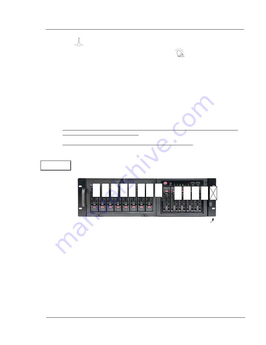
Installing drives into the Aurora LS Figure 2.2
The Galaxy Aurora LS features 12 removable drives. They have been shipped separately to
insure the Aurora LS would not incur shipping damages from a possible shipping related
shock to the drives or backplane.
CAUTION
: Be aware that the Aurora LS’s file system does not support drive
roaming. Drives must be installed and must be placed into their prepared slots for the RAID
set to operate properly.
The drives will be tagged with numbers 1-12. Place them in their assigned numbered slot in
the Aurora LS chassis as shown below.
NOTE THAT DRIVE SLOT 13 HAS AN EMPTY DRIVE CANISTER!
The drives are simple to install. Simply unwrap and push each drive into each empty drive
opening as far as it will go, then push the handle in until the red button clicks into place. Each
of the drive modules in the Galaxy Aurora LS has two LEDs the upper LED flashes for disk
activity, while the lower LED is used for errors and flash ID use. The RAID’s EOS software will
automatically find all drives. To remove a drive module, push the red button until the black
handle pops out. Then pull the handle until it is sticking straight forward, and carefully pull the
drive out by the handle. To reinstall a drive, make sure the handle is sticking out of the module
(if it's not, push the red button to release the handle),
The Aurora LS OS has been preloaded and RAID storage preconfigured to be ready for you to
power up and start configuring it for use. Before powering up, make the cable connections to ,
ethernet, power, keyboard, and monitor [ in certain cases these components and cables are
provided].
Figure 2.2
1
2
3
4
5
6
7
8
9
10
11
12
X Not Used


