29
2.
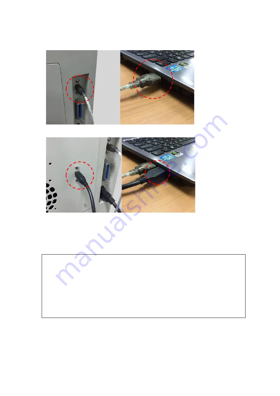
After installation of the printer driver and SmartCONTROL Vision software, please connect the USB cable
between computer and the laser machine
3.
Connect the 2nd USB cable between computer and the SmartVISION
TM
Pro CCD connection port
4.1.2.2 Ethernet Connectivity
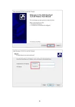
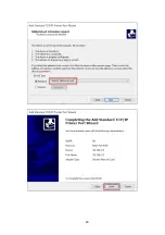
Connect the Ethernet Cable in accessory to the Ethernet port on the right-hand side of the laser system. Follow
below instruction for Ethernet connectivity setup.
NOTE
1.
Never leave laser system unattended during laser cutting, engraving, and marking process, even
with Ethernet or Wi-Fi connection setup, this requirement cannot be avoided. Exposure to the
laser beam may cause ignition flame to combustible materials.
2.
DO NOT connect USB cable when using Ethernet function for data transmission.
3.
If you have purchased additional Optional Accessories for the LV-290, please refer to chapter 7
for instructions on how to properly setup your optional accessories. These should be setup prior
to working with your LV-290.
Summary of Contents for LV-290
Page 1: ......
Page 25: ...23 3 Chapter 3 Mechanical Overview Front View Top View Right View Left View Rear View...
Page 34: ...32...
Page 35: ...33...
Page 36: ...34...
Page 41: ...39...
Page 42: ...40...
Page 50: ...48 3 Click Next 4 The installation would be finished in few seconds...
Page 74: ...72 5 1 4 Graphic Control Panel Navigation Chart...
Page 185: ...183...
Page 187: ...185...
Page 199: ...197 Cutting edges achieved with the different lenses...
Page 211: ...209 9 Chapter 9 Basic Troubleshooting...
Page 213: ...211 10 Chapter 10 Appendix Glossary Specification Sheet...
Page 216: ...FA01785 R1 190805...


