195
7)
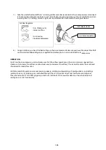
Take the unattached end of the ¼" air tubing (other end already connected to air compressor) and connect
it to the air tube connector on the air assist valve. Make sure you press down on the air tube fastener when
inserting the ¼" air tubing, to form a tight, secure attachment as indicated in the diagram below.
Air Flow Regulator
8) Congratulations, you have finished setting up the air compressor. Make sure you have the proper SmartAIR
nozzle installed (depending on your application), before you turn on and utilize the air compressor.
OPERATION:
Switch on the air compressor unit and make sure that the airflow regulator on the air assist value is opened (turn
clockwise to increase the airflow, counter-clockwise to decrease the airflow). The air nozzle under the laser head
should emit a steady flow of air.
With the SmartAIR nozzle and air compressor properly installed and operating, all configurations and settings
relating to air-assist functions are controlled through the LV-290 printer driver and hardware control panel.
Please refer to the LV-290 PEN page on print driver section of this manual for details on how to enable and
configure air-assist functionality.
Turn Clockwise to
increase airflow
Turn Counter-
Clockwise to decrease
Air Tube Fastener
Air Tube Connector
Summary of Contents for LV-290
Page 1: ......
Page 25: ...23 3 Chapter 3 Mechanical Overview Front View Top View Right View Left View Rear View...
Page 34: ...32...
Page 35: ...33...
Page 36: ...34...
Page 41: ...39...
Page 42: ...40...
Page 50: ...48 3 Click Next 4 The installation would be finished in few seconds...
Page 74: ...72 5 1 4 Graphic Control Panel Navigation Chart...
Page 185: ...183...
Page 187: ...185...
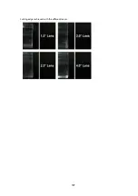
Page 199: ...197 Cutting edges achieved with the different lenses...
Page 211: ...209 9 Chapter 9 Basic Troubleshooting...
Page 213: ...211 10 Chapter 10 Appendix Glossary Specification Sheet...
Page 216: ...FA01785 R1 190805...

