205
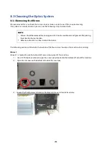
4) Loosen the thumbscrew securing mirror #1.
5) Clean the mirror in the proper manner.
6) Place the mirror back to the optics holder after cleaning.
7) Tighten the thumbscrew.
8) Close and secure all the covers.
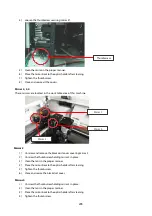
Mirror 2, 3, 4
These mirrors are located in the work table area of this machine.
Mirror 2
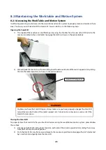
1) Unscrew and remove the black dust cover covering mirror 2.
2) Unscrew the thumbscrew holding mirror 2 in place.
3) Clean the lens in the proper manner.
4) Place the mirror back to the optics holder after cleaning.
5) Tighten the thumbscrew.
6) Close and secure the black dust cover.
Mirror 3
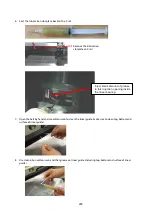
1) Unscrew the thumbscrew holding mirror 3 in place.
2) Clean the lens in the proper manner.
3) Place the mirror back to the optics holder after cleaning.
4) Tighten the thumbscrew.
Mirror 4
Thumbscrew
Mirror 2
Mirror 3
Summary of Contents for LV-290
Page 1: ......
Page 25: ...23 3 Chapter 3 Mechanical Overview Front View Top View Right View Left View Rear View...
Page 34: ...32...
Page 35: ...33...
Page 36: ...34...
Page 41: ...39...
Page 42: ...40...
Page 50: ...48 3 Click Next 4 The installation would be finished in few seconds...
Page 74: ...72 5 1 4 Graphic Control Panel Navigation Chart...
Page 185: ...183...
Page 187: ...185...
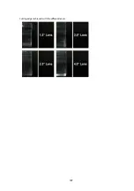
Page 199: ...197 Cutting edges achieved with the different lenses...
Page 211: ...209 9 Chapter 9 Basic Troubleshooting...
Page 213: ...211 10 Chapter 10 Appendix Glossary Specification Sheet...
Page 216: ...FA01785 R1 190805...

