194
3)
Connect a 1/4" tubing to the air tube fastener valve on the air compressor.
NOTE
It is important that the ¼" air tubing has clean, straight cuts on each end. Jagged or slanted cuts will
not produce adequate sealing capabilities.
4)
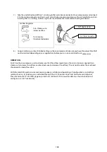
Open the bottom front doors of this machine to locate both the Air-Assist
Valve and Internal Power Sockets. As indicated below:
5)
Plug the air compressor’s power cord A into the AC internal power socket.
6)
Plug the female end of power cord B to the AC internal power socket and the male end to an external power
outlet.
Air Assist Valve located at
bottom right side for 100W
models
Air Assist Valve
AC Internal Power
Sockets
Power Cord A Socket
Power Cord B Socket
Summary of Contents for LV-290
Page 1: ......
Page 25: ...23 3 Chapter 3 Mechanical Overview Front View Top View Right View Left View Rear View...
Page 34: ...32...
Page 35: ...33...
Page 36: ...34...
Page 41: ...39...
Page 42: ...40...
Page 50: ...48 3 Click Next 4 The installation would be finished in few seconds...
Page 74: ...72 5 1 4 Graphic Control Panel Navigation Chart...
Page 185: ...183...
Page 187: ...185...
Page 199: ...197 Cutting edges achieved with the different lenses...
Page 211: ...209 9 Chapter 9 Basic Troubleshooting...
Page 213: ...211 10 Chapter 10 Appendix Glossary Specification Sheet...
Page 216: ...FA01785 R1 190805...


