background image

Trying Out the Instrument

R&S

®

RTE

71

Getting Started 1326.1026.02 ─ 06

4. Close the dialog box.

To save screenshots

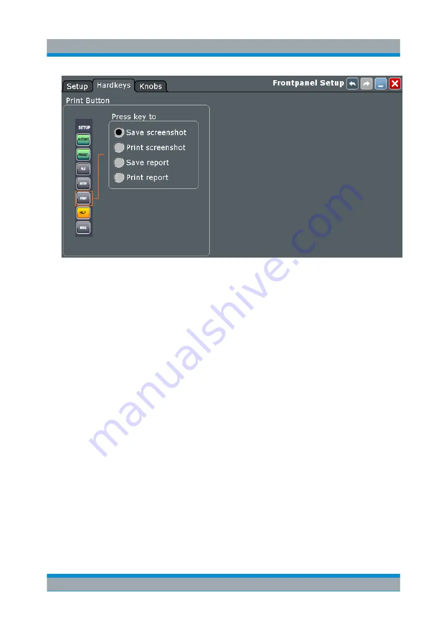
1. Press the PRINT key.

2. Change the horizontal scale.

3. Press the PRINT key.

The files are saved to the following directory:

C:\Users\Public\Public Documents\Rohde-Schwarz\RTx\
ScreenShots

The default file name is 

Screenshot_<date>_<index>_<time>.png

.

4. To access the saved files, open the "File" menu and tap "Minimize Applica-

tion".

5. Double-tap the "User" folder icon on the desktop.

6. Open the 

ScreenShots

 folder.

Printing and Saving Screenshots

Summary of Contents for RTE-COM4

Page 1: ...R S RTE Digital Oscilloscope Getting Started Getting Started 1326 1026 02 06 J J2...

Page 2: ...d 1317 2500K02 R S RTE1104 1 GHz 4 channels 1326 2000K64 and 1317 2500K04 R S RTE1152 1 5 GHz 2 channels 1326 2000K72 R S RTE1154 1 5 GHz 4 channels 1326 2000K74 R S RTE1202 2 GHz 2 channels 1326 2000...

Page 3: ...e of the product The product is used for its designated purpose if it is used in accordance with its product documentation and within its performance limits see data sheet documentation the following...

Page 4: ...ation item 7 Signal words and their meaning The following signal words are used in the product documentation in order to warn the reader about risks and dangers Indicates a hazardous situation which i...

Page 5: ...afety is not observed either at all or to the extent necessary electric shock fire and or serious personal injury or death may occur 1 Prior to switching on the product always ensure that the nominal...

Page 6: ...t be fuse protected in such a way that anyone who has access to the product as well as the product itself is adequately protected from injury or damage 14 Use suitable overvoltage protection to ensure...

Page 7: ...masks and protective clothing must be worn 7 Laser products are given warning labels that are standardized according to their laser class Lasers can cause biological harm due to the properties of the...

Page 8: ...ckaging until they are ready to be used 4 Cells and batteries must not be exposed to any mechanical shocks that are stronger than permitted 5 If a cell develops a leak the fluid must not be allowed to...

Page 9: ...back obligations and disposal obligations for manufacturers within the EU Contact your Rohde Schwarz customer service center for environmentally responsible disposal of the product 3 If products or th...

Page 10: ...ument up to date and to be informed about new application notes related to your instrument please send an e mail to the Customer Support Center stating your instrument and your wish We will take care...

Page 11: ...ns Used in the Documentation 10 1 3 1 Typographical Conventions 10 1 3 2 Conventions for Procedure Descriptions 10 2 Preparing for Use 11 2 1 Unpacking and Checking the Instrument 11 2 2 Positioning t...

Page 12: ...he Instrument 39 4 1 Displaying a Basic Signal 39 4 2 Acquiring Data 41 4 3 Changing the Waveform Scaling and Position 42 4 4 Zooming into the Display 48 4 4 1 Using the Standard Zoom 48 4 4 2 Using t...

Page 13: ...the Touchscreen 80 5 3 App Cockpit 82 5 4 Working with Waveforms 83 5 5 Using the Signal bar 87 5 6 Toolbar 89 5 6 1 Using the Toolbar 90 5 6 2 Configuring the Toolbar 91 5 6 3 Toolbar Functions 92 5...

Page 14: ...Contents R S RTE 6 Getting Started 1326 1026 02 06 6 3 Setting the Display Language 108 6 4 Adjusting Passive Probes 109 Index 111...

Page 15: ...uisition rate and shortest blind time Access and analyze prior waveforms in the memory using the history function Get fastest results even with maximum data with hardware accelerated pro cessing mathe...

Page 16: ...ve access to the functional description directly on the instrument User manual Describes all instrument functions in detail It also provides an introduction to remote control a complete description of...

Page 17: ...specific characteristics See www rohde schwarz com brochure datasheet rte 1 2 3 Release Notes Open Source Acknowledgment The release notes list new features improvements and known issues of the cur re...

Page 18: ...inks Links that you can click are displayed in blue font References References to other parts of the documentation are enclosed by quotation marks 1 3 2 Conventions for Procedure Descriptions When ope...

Page 19: ...strument from its packaging and check the equipment for com pleteness proceed as follows 1 Pull off the polyethylene protection pads from the instrument s rear feet 2 Carefully remove the pads from th...

Page 20: ...a horizontal bench with even flat surface The instrument can be used in horizontal position standing on its feet or with the support feet on the bottom extended Risk of injury if feet are folded out...

Page 21: ...eed to stack more than three instruments install them in a rack The overall load imposed on the lowest instrument must not exceed 500 N It is best if all instruments have the same dimensions width and...

Page 22: ...ns are unimpeded and that the minimum distance from the wall is 10 cm 2 3 Starting the Instrument Risk of injury and instrument damage The instrument must be used in an appropriate manner to prevent e...

Page 23: ...ibed in the following sections The ambient temperature does not exceed the range specified in the data sheet Signal levels at the input connectors are all within the specified ranges Signal outputs ar...

Page 24: ...S RTE is connected to the AC power supply and the main power switch on the rear panel is in position I 2 Press the POWER key on the front panel The instrument performs a system check boots the Window...

Page 25: ...the rear panel switch or by disconnecting the power cord the instrument loses its current settings Fur thermore program data can be lost Press the POWER key first to shut down the application properl...

Page 26: ...alling USB devices on R S RTE is easy under the Windows operating sys tem because all USB devices are plug play After a device is connected to the USB interface Windows automatically searches for a su...

Page 27: ...use to configure the mouse properties Connecting a printer When printing a file the instrument checks whether a printer is connected and turned on and whether the appropriate printer driver is install...

Page 28: ...nitor select Projector only To show the instrument s display content on both the oscilloscope and the external monitor select Duplicate The touchscreen of the R S RTE has a screen resolution of 1024 x...

Page 29: ...een with its control elements 3 1 Front Panel The front panel of the R S RTE is shown in Figure 3 1 The function keys are grouped in functional blocks to the left and the right of the touchscreen Belo...

Page 30: ...example Never use cleaning agents to clean the outside of the instrument Use a soft dry lint free dust cloth instead 3 1 1 Input Connectors The R S RTE has two or four channel inputs to connect the in...

Page 31: ...eak When performing measurements in circuits with transient overvoltages of category II III or IV circuits make sure that no such overvoltages reach the R S RTE input Therefore use only probes that co...

Page 32: ...e printer and USB flash drive Note Electromagnetic interference EMI can affect the measurement results To avoid any impact do not use USB connecting cables exceeding 1 m PROBE COMPENSATION Probe compe...

Page 33: ...ure or waveform generator R S RTE B6 or GPIB connector R S RTE B10 9 Kensington lock slot to secure the instrument against theft 10 Lugs to attach the accessory bag AC power supply connector and main...

Page 34: ...pter 2 4 2 Connecting an External Monitor on page 19 TRIGGER OUTPUT The SMA connector for external trigger output is used to provide the internal trig ger signal of the oscilloscope to trigger other i...

Page 35: ...or detailed specifications refer to the data sheet RTE B6 Optional connectors for the waveform generator option R S RTE B6 For detailed specifications refer to the data sheet GEN1 GEN2 BNC connectors...

Page 36: ...loses the Setup dialog box where you can Access Windows configuration and install firmware updates Configure the touchscreen Check and install option keys for software options Check availability of ha...

Page 37: ...veform intensity is adjusted Press the knob to toggle between the three settings The controlled parameter and its value are shown in the input box in the upper left cor ner of the screen 3 3 2 HORIZON...

Page 38: ...tion of the waveform or the position of the reference point on the screen Press the knob to toggle the setting The controlled parameter and its value are shown in the input box in the upper left corne...

Page 39: ...waveform is selected Pressing the key opens the Vertical dialog box for the appropriate channel The vertical rotary knobs are focused on the selected waveform and they are illu minated in the color of...

Page 40: ...l location in divisions Offset moves the vertical center of the selected channel to the offset value The knob lights up in the color of the selected waveform SCALE This rotary knob adjusts the vertica...

Page 41: ...shown on the trigger label which is in the upper part of the sig nal bar on the touchscreen MODE Toggles the trigger mode between Auto and Normal The current setting is shown on the trigger label RUN...

Page 42: ...ement for the active waveform and displays the Measurement result box If you press the MEAS key while a measurement is enabled the Measurements dialog box is displayed where you can Configure amplitud...

Page 43: ...of search results LOGIC Opens the dialog box for configuration of parallel buses and digital channels The key lights up if you enable at least one parallel bus You can switch off the selected bus usi...

Page 44: ...ram areas and mask points in input boxes press to toggle the parameter turn clockwise to increase the value or turn counterclockwise to decrease it To move zoom area cursor line or gate in diagrams Tu...

Page 45: ...has only horizontal tabs the key switches the horizontal tabs In a dialog box that has horizontal and vertical tabs the key switches the verti cal tabs preferably If the focus is on a horizontal tab i...

Page 46: ...is located on the lower left corner of the front panel It starts up and shuts down the instrument s software The light of the key shows the instrument state Orange standby the main power switch is on...

Page 47: ...uments Try out the following Displaying a Basic Signal 39 Acquiring Data 41 Changing the Waveform Scaling and Position 42 Zooming into the Display 48 Displaying the Waveform History 50 Showing Basic M...

Page 48: ...de 4 If necessary compensate the passive probe as described in Chapter 6 4 Adjusting Passive Probes on page 109 5 In the TRIGGER area of the front panel press the SOURCE key Press the key again to swi...

Page 49: ...aver age waveforms If you need to change only one setting during analysis and you need to change it often you can reduce the dialog box to a small box that only contains the required setting Thus you...

Page 50: ...Tap the Maximize icon in the mini dialog box The complete Acquisition dialog box is restored 8 Close the dialog box by tapping 4 3 Changing the Waveform Scaling and Position As you can see on the y ax...

Page 51: ...ickly find the new trigger level and try out the scaling functions 1 Press the CH1 key on the front panel in the VERTICAL area to display the Vertical dialog box 2 Change the Coupling to AC Close the...

Page 52: ...ess the CH1 key again b Enter 0 V in the Offset field The waveform is now displayed in the center of the display with the x axis crossing at 0 V The waveform might be unstable if the trigger level is...

Page 53: ...Instrument R S RTE 45 Getting Started 1326 1026 02 06 5 Tap the Find level icon on the toolbar The instrument adjusts the trigger level and a stable waveform is displayed Changing the Waveform Scalin...

Page 54: ...ore detail turn the horizontal Scale rotary knob The current scale factor per division is displayed in the upper left hand corner of the display while you turn the knob You can switch between a small...

Page 55: ...ntil you perform a different action Tip Instead of using the UNDO and REDO keys you can tap the correspond ing icons on the toolbar If you use an active single ended probe you can measure the DC compo...

Page 56: ...ting Started Zoom 4 4 1 Using the Standard Zoom 1 Restore the default signal channel settings by pressing the PRESET and AUTOSET keys 2 On the toolbar tap the Zoom icon 3 Tap the position in the diagr...

Page 57: ...om window and make room on the display for other results tap the Delete icon and then the zoom window 4 4 2 Using the Fingertip Zoom 1 Touch the Zoom icon on the toolbar and drag it down until the Zoo...

Page 58: ...p zoom into a standard zoom diagram 4 5 Displaying the Waveform History During a continuous acquisition the instrument stores the acquired data in the memory and shows the current acquisition on the d...

Page 59: ...access History dialog box appears and the history mode is enabled 6 Tap Play The ten stored waveforms are displayed one after the other but very fast 7 In the Current acq field enter 4 to display the...

Page 60: ...e results in the result table corresponds with the source waveform color 4 6 1 Performing a Cursor Measurement 1 Restore the default signal channel settings Press the PRESET and AUTOSET keys 2 Tap the...

Page 61: ...he display for other results tap the red cross on the icon label 4 6 2 Performing Automatic Amplitude Measurements You can start up to 8 automatic measurements to run in parallel The Automatic measurm...

Page 62: ...e Automatic measurment icon again Then tap the waveform By default the measurement of the low signal level is started 4 Tap the Automatic measurment icon again Then tap the waveform By default the amp...

Page 63: ...trument R S RTE 55 Getting Started 1326 1026 02 06 7 Select Rise time 8 In the Meas2 line tap the measurement type button labeled Low 9 Select Fall time 10 Under Statistics tap Enable Showing Basic Me...

Page 64: ...ource can be performed at once simply by tapping the Quick measurement toolbar icon The results are displayed in a result box You can configure the measurement types to be inclu ded in quick measureme...

Page 65: ...urements dialog box 5 If necessary select the Quick Meas tab 6 Scroll down in the table and disable the Mean and RMS measurements 7 Tap Activate and select Period Now the result box also shows the res...

Page 66: ...rtant results are displayed and updated in the result icon as well Do not close the result icon as you need the results for the Search example see Chapter 4 9 Performing a Search on page 65 4 6 4 Disp...

Page 67: ...ram and a vertical histogram is defined and displayed 3 To display the measurement results for the histogram tap the Measurement icon on the toolbar 4 Tap the histogram The waveform count for the hist...

Page 68: ...FFT analysis a signal in the time domain is converted to a spectrum of frequencies A basic spectrum waveform can be displayed quickly The usage of FFT is also shown in a short video that is available...

Page 69: ...tting Started 1326 1026 02 06 3 To measure the spectrum on the math channel tap the Measurement icon on the toolbar 4 Tap the spectrum waveform The spectrum measurement results are displayed in a resu...

Page 70: ...ting Started 1326 1026 02 06 5 Double tap the spectrum waveform The FFT Setup dialog box opens 6 Set the Center frequency to 10 kHz The instrument adjusts the frequency span automatically Close the di...

Page 71: ...x 9 To remove the FFT results tap the Delete icon and then the spectrum wave form 10 Close the Measurement result box 4 8 Performing Mathematical Calculations In addition to the measured waveforms you...

Page 72: ...er b enter the vertical position offset e g 2 Look at the lower part of the dialog box and note that the instrument adjusts the Vertical scale and Vertical offset of the math waveform automatically 8...

Page 73: ...the results of the measurement example described in Chapter 4 6 3 Performing and Configuring the Quick Mea surement on page 56 1 Press the SEARCH key on the front panel ANALYSIS area 2 Select C1 as So...

Page 74: ...ershoots of the last acquisition are listed in the search result table The search zoom window shows the last result that was found Vertical lines indicate the time values for which a result was found...

Page 75: ...r points of one complete pulse with a minor offset to the inside To finish the mask definition double tap the last point Tip To create an exact rectangle draw the diagonal of the rectangle on the scre...

Page 76: ...ich the values of the positive pulse should remain 7 Tap the icon in the result box and select the Test Definition tab 8 Select channel 1 as the Source 9 Define the number of tolerable sample hits in...

Page 77: ...your results In the following examples you print the current display as a black and white graphic with inverted colors i e a black waveform is printed on a white background Then you save some screensh...

Page 78: ...ap the upper left button and select the printer 5 Tap Print The result is a monochrome image 6 Close the dialog box To configure the PRINT key 1 Open the File menu and tap Frontpanel Setup 2 Select th...

Page 79: ...the PRINT key The files are saved to the following directory C Users Public Public Documents Rohde Schwarz RTx ScreenShots The default file name is Screenshot_ date _ index _ time png 4 To access the...

Page 80: ...ont panel in the SETUP area on the left 2 Select the Waveforms Results tab 3 Select the Waveforms tab 4 Check the Source 5 Set Scope to Full Waveform Tip If a cursor zoom or measurement gate is define...

Page 81: ...p Data logging to enable export all waveforms of a running acquisition d Enter Acq count 10 the number of subsequent waveforms that the instrument acquires and saves 4 Tap Start Export to save the wav...

Page 82: ...ing settings Saving and restoring device settings 1 Press the FILE key on the front panel 2 Select the Save Recall tab 3 Select the Settings tab 4 Tap Save As Enter the path and file name C Users Publ...

Page 83: ...file transfer Even on computers with non Windows operating systems a remote desktop connection is possible using RDP applica tions See also User Manual chapter Remote Desktop Connection Remote monito...

Page 84: ...tion keys and rotary knobs The front panel provides nearly all functions and controls to operate the instru ment in the classic ways without touchscreen As an exception the signal bar cannot be used w...

Page 85: ...aveform 3c 4 Trigger level 5 Trigger position 6 Reference point distance from trigger position to reference point horizontal position 7 Zoom area 8 Zoom diagram 9 Histogram area 10 Histogram 11 Messag...

Page 86: ...shows the vertical and horizontal divisions The division lines are labeled with the correspondent values The grid labels have the color of the waveform to which they belong If several waveforms are sh...

Page 87: ...l on the signal bar 1 Vertical position 2 Offset 3 Vertical scale 4 Coupling You can also adjust the behavior of the signal bar in various ways see Chap ter 5 5 Using the Signal bar on page 87 Trigger...

Page 88: ...ilities are described in detail in the User Manual chapter Zoom Histogram and histogram area 9 10 A histogram shows the frequency of occurrence of voltage or time values in a bar chart directly in the...

Page 89: ...r 3 on page 78 3 Menu bar 4 Dialog box 5 Tab in a dialog box 6 Result box 7 Input box Toolbar 1 The icons on the toolbar provide quick and easy access to the most important functionality For a detaile...

Page 90: ...nding dialog box to adjust the settings For details see Chapter 5 7 Displaying Results on page 97 Input box 7 The input box appears if you adjust a value using one of the rotary knobs or if you drag a...

Page 91: ...r comparison and analysis Math waveforms Four mathematic waveforms can be created with mathematic operations per formed on channel reference and other math waveforms Zoom waveforms Show the details of...

Page 92: ...e the other To change the diagram name double tap the tab name The Rohde Schwarz SmartGrid function helps to arrange the diagrams Waveform states Depending on its place on the screen and the effect of...

Page 93: ...he signal icon Note Zoom waveforms in zoom diagrams cannot be selected To minimize a waveform Choose on of the following ways Tap the Minimize icon in the upper right corner of the waveform s signal l...

Page 94: ...pears and a blue area shows where the waveform will be placed 2 Drop the waveform in the target area The waveform appears in an existing or in a new diagram and it is selected for further actions 3 To...

Page 95: ...ect the waveform and then press the SIGNAL OFF key To switch off a minimized waveform tap the Close icon in the upper right corner of the minimized signal view Disable Show channel in the Vertical Cha...

Page 96: ...p of the signal bar and drag it to the opposite side of the screen To configure auto hide The signal bar can be hidden if the displayed information has not changed for a defined time and is displayed...

Page 97: ...Colors Define the new color settings To see the effect of a setting change in the Preview area enter the value and press the ENTER key 6 Tap OK The signal bar is displayed in the new colors 5 6 Toolb...

Page 98: ...ge 85 2 Tap the icon of the function in the toolbar 3 To define the analyzed area do one of the following Tap the required diagram Drag a rectangle on the diagram To select a function on a toolbar men...

Page 99: ...ferences It is retained when you switch off and on the instrument and you can save it in the user preferences and user defined preset 1 On the Display menu select Toolbar 2 Select the functions to be...

Page 100: ...t Clear Screen Delete Autoset and Preset Label Run Stop and Run Single Update Ref Waveform Save Waveform Spectrogram option R S RTE K18 You can configure the content of the toolbar and hide the date t...

Page 101: ...the required set tings Find Trigger Level Analyses the signal and sets the trigger level to the middle of the signal peaks Zoom The zoom icon on the toolbar shows the last selected zoom type A short t...

Page 102: ...using the Navigation knob Search Performs a search according to the settings in the Search Setup dialog box Tap the icon and then tap the diagram with the waveform to be searched or drag a rectangle...

Page 103: ...am area to open the Histogram dialog box Measurement Starts an automatic measurement You can start up to 8 automatic measurements to run in parallel The Automatic measurment icon starts the measuremen...

Page 104: ...LE Save Recall Set tings Save Screenshot Saves a screenshot of the current display using the settings defined in File menu Print Setup Create Report Creates a report of the current measurement setting...

Page 105: ...e waveform data to file using the settings defined in FILE Waveforms Results Waveforms The filename is created according to the autonaming pattern Tap the icon and then tap the waveform to be exported...

Page 106: ...he diagram If you drop the box on the signal bar a result icon is created If you drop the box somewhere else a floating result box is created 1 Floating result box 2 Table in a tab on the left or righ...

Page 107: ...u can control the instrument intuitively with the touchscreen This section pro vides an overview of the accessing methods and describes how to use the dialog boxes Each dialog box has four icons in th...

Page 108: ...t you need to modify 2 Tap the Minimize icon in the upper right corner of the dialog box The dialog box turns into a small box that contains only the Wfm Arithmetic setting 3 To restore the complete d...

Page 109: ...u turn a knob the input box appears the upper left corner of the screen show ing the parameter name and current value Using rotary knobs 1 Turn the knob to change the value 2 To toggle the increment t...

Page 110: ...between small steps and large steps tap the Steps icon To get the value that was used before the keypad was displayed tap Cur To enter a user defined value tap the numbers and complete the entry by ta...

Page 111: ...nter numeric data in a dialog box with navigation controls 1 To navigate to the entry field press the FIELD and FIELD keys 2 To change the value with a small step size turn the rotary knob Alternative...

Page 112: ...se the following sources Tutorials demonstrate the general usage of the R S RTE for example how to use the SmartGrid Tooltips give a short description of the parameter The context help provides functi...

Page 113: ...he tooltip icon disables automatically when you tap a parameter To show another tooltip tap the tooltip icon again To open general help Press the yellow HELP button on the left side of the screen If a...

Page 114: ...ew tab with the corresponding help topic is displayed To search topics for a text string 1 Switch to the Search tab 2 Select the Keyboard icon besides the entry field 3 Enter the string you want to fi...

Page 115: ...sic hardware check Recommendation on performing the self alignment When putting the instrument into operation for the first time After a firmware update Once a week When major temperature changes occu...

Page 116: ...the instrument has been changed and you cannot look straight on the screen If another person operates the instrument If you notice that touching a specific point on the screen does not achieve the cor...

Page 117: ...ent the first time Compensation matches the probe cable capacitance to the oscilloscope input capacitance to assure good amplitude accuracy from DC to upper bandwidth limit frequencies A poorly compen...

Page 118: ...Setting Up the Instrument R S RTE 110 Getting Started 1326 1026 02 06 Adjusting Passive Probes...

Page 119: ...s Probe compensation 24 Rear panel 24 USB 24 Coupled zoom quick access 94 CURSOR key 34 Cursors Minimizing results 52 Quick access 94 Trying out 52 D Data entry 101 Data sheet 9 Decimation 41 Delete 9...

Page 120: ...ctor 26 Language Changing 108 LEVELS knob 33 Lock touchscreen 28 LOGIC key 35 Logic probe connector 27 M Markers Example 48 Mask test Quick access 94 Trying out 66 MASKS key 35 MATH key 31 Math wavefo...

Page 121: ...LEN key 29 Resolution Rotary knob 30 Result boxes 80 Background transparency 29 Displaying 97 Results Configuring display 97 Rotary knobs Trying out 42 RTE B10 27 Run 33 RUN CONT key 33 RUN N SINGLE k...

Page 122: ...ndo 92 Zoom 93 Tooltips 93 Show 105 Touchscreen Adjusting 108 Compared with mouse 75 Control elements 80 Lock unlock 28 Usage 75 Transparency 29 Trigger Controls 32 External input 22 External output 2...

Page 123: ...Index R S RTE 115 Getting Started 1326 1026 02 06 Z Zoom Area 80 Diagram 80 Fingertip 49 Quick access 93 Standard 48 Trying out 48 ZOOM key 34 Zoom waveforms 83...

Reviews: