Node Controller Overview
Node Controller Communications
Node Controller Hardware User Manual
43
Rockwell Automation Publication MMI-UM013B-EN-P - April 2020
Configuration Recommendations
•
Recommended Ethernet addressing scheme (see
):
Network.Path.Motor
•
Network addresses are used for network configuration.
•
Path 0 addresses are used for Subnet configuration:
x.y.0.m
Where:
m
– Node controllers/Network devices
•
Path p addresses are used for motors on that path:
x.y.p.m
Where:
p
– path
m
– motor
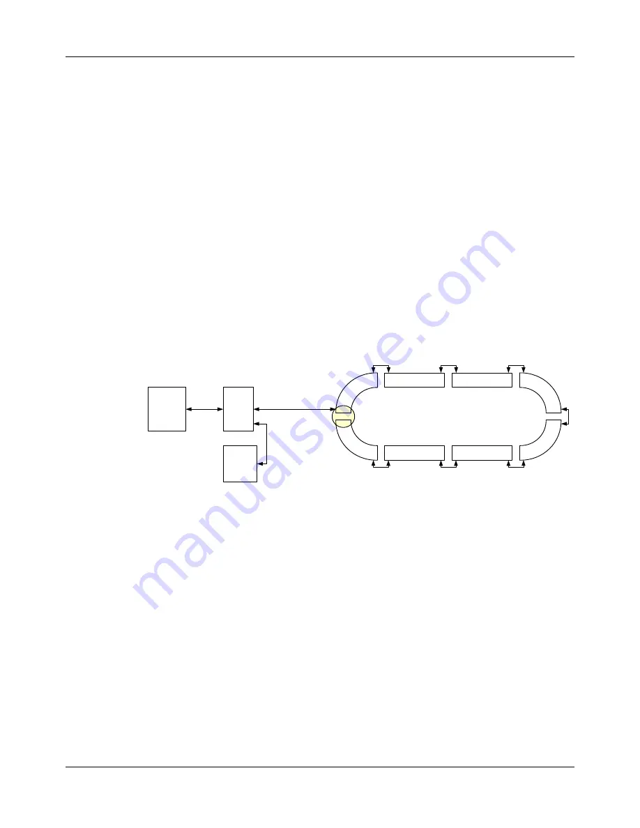
Figure 3-1: Ethernet Motor Wiring Example
•
Switches are two logical track paths, only one IP address is assigned.
•
Maximum number of motors per Ethernet chain = 50.
•
Factory network design must minimize extra traffic on the physical network that the
transport system is using.
•
Only use Chain or Star Ethernet connection topologies.
•
Closed-loop (ring) Ethernet connections must be avoided (industry standard
Ethernet practice) to help prevent network saturation.
•
Large amounts of traffic can degrade the performance of the transport system.
Only pass transport system communication through the Ethernet chains in the
transport system.
•
Standard IP UDP communication, low latency.
•
100BASE-TX Fast Ethernet (IEEE 802.3u) compliant.
•
Minimum of CAT 5 cabling is required.
HLC &
Node
Controller
Host
Controller
Enet
Switch
Relay
Enet Motor
Enet Motor
Loop Transport System:
One Enet Connection, One Chain
One Path
Enet Motor
Enet Motor
x.y.0.10
P1M1
x.y.1.1
P1M2
x.y.1.2
P1M3
x.y.1.3
P1M4
x.y.1.4
P1M5
x.y.1.5
P1M6
x.y.1.6
P1M7
x.y.1.7
P1M8
x.y.1.8
Enet
Motor
Enet
Motor
Enet
Motor
Enet
Motor


