


62
Rockwell Automation Publication 20P-TG004C-EN-P - September 2021
Chapter 3
Access Procedures
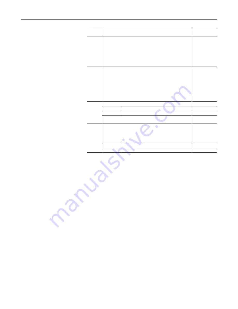
S14
Field current resistors setting.
In addition, the value selected with switch S14 must be entered in Par 374 [Rated
Field Curr] in the control software when the drive is commissioned.
S14-1 =
S14-2 =
S14-3 =
S14-4 =
S14-5 =
S14-6 =
S14-7 =
S15
Configuration of the control circuit board to the appropriate drive size. This value is
set to the appropriate size at the factory.
S15-1 =
S15-2 =
S15-3 =
S15-4 =
S15-5 =
S15-6 =
S15-7 =
S15-8 =
S20
Monitoring of the Z channel of the digital encoder on connector XE2:
Off Position
Z-channel monitored
On Position
Z-channel not monitored
The S20 setting should match the value selected in Par 652 [Encoder Err Chk] (for
example, if S20 = “Off”, then Par 652 = 1 “Enabled”).
S21
Encoder power supply voltage and input adaptation selection:
This switch setting determines both the power supply (input) and feedback level
(output) voltage of the connected encoder.
Note: When control power is supplied to the drive, the appropriate LED lights to
indicate the selection of the switch.
ENC_5
+5 V encoder (+2.5…5.4V input range)
ENC_12
+12…15 V encoder (+5.4V…15.2V input range)
Jumper/
Switch
Function
Setting


