Pub. 1147 - Rev. 7 SEPTEMBER 2004
27
Mechanical Dock Leveler Hydraulic Conversion
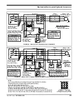
Motor – 1 HP
@3450 RPM, 480V,
3 Ph., 50/60 Hz.
Branch Circuit Disconnect
Control Box
Motor
Junction Box
L1
L2
L3
1L1
480V
120V
"Raise"
H1 H3
H2
X1
X2
4
5
5A
MCR
O/L
H4
1L2
1L3
T1
T2
T3
T1
T2
T3
G
T1
T2
T3
MCR 1 O/L
Set @
2.2 Amp
MCR 2 O/L
MCR 3 O/L
G
Transformer
Secondary Fusing,
0.5 Amp, 250V
(3 AG Slow Blow)
Optional
Door Interlock
Limit Switch
(By Others)
Use Min. #12 Gage
60 / 75 C Copper
Wire /100 Ft. Of Run
Transformer Primary Fusing
0.5 Amp, 600V, Class CC With
Rejection Feature (Typ. 2 Places)
IMPROTANT
Motor Lead Connections
= Wire Termination
Wire Nut Or Equal Device
50 VA Transformer For
Hydraulic Controls Only.
Do Not Use To Power
Auxiliary Equipment.
CAUTION
Remove Jumper Wire
Between Terminals 5
And 5A When Installing
Optional Door Interlock
Limit Switch.
FIGURE 24 - 480 VOLT 3 PHASE 50/60 HZ. SCHEMATIC
Branch Circuit Disconnect
Control Box
Motor
Junction Box
L1
L2
L3
1L1
480V
120V
"Raise"
H1 H3
H2
X1
X2
4
5
5A
MCR
O/L
H4
1L2
1L3
T1
T2
T3
4
5
10
10
4
5
4
5
T1
T2
T3
G
T1
T2
T3
MCR 1 O/L
Set @
2.2 Amp
MCR 2 O/L
MCR 3 O/L
G
Transformer
Secondary Fusing,
0.5 Amp, 250V
(3 AG Slow Blow)
Optional
Door Interlock
Limit Switch
(By Others)
LS1 (N.O.H.C.)
Restrictor Sw.
LS2 (N.O.)
ARTD Limit Sw.
Motor – 1 HP
@3450 RPM,480V,
3 Ph., 50/60 Hz.
Use Min. #12 Gage
60 / 75 C Copper
Wire/ 100 Ft. Of Run
Motor Lead
Connections
= Wire
Termination
Wire Nut Or
Equal Device
Transformer Primary Fusing
0.5 Amp, 600V, Class CC With
Rejection Feature (Typ. 2 Places)
50 VA Transformer For
Hydraulic Controls Only.
Do Not Use To Power
Auxiliary Equipment.
CAUTION
IMPORTANT
Remove Jumper Wire Between
Terminals 5 And 5A When Installing
Optional Door Interlock Limit Switch.
FIGURE 25 - 480 VOLT 3 PHASE 50/60 HZ. SCHEMATIC WITH OPTIONAL ARTD SYSTEM
NOTES:
From Customer Main Power And Safety Protection Device 480V 3 Ph. 50/60 Hz.
4 Amp Dual Element Fuse (Fused Disconnect Supplied By Others)
One Leveler Per Overload Protection Device. [Ref. N.E.C. 1999 Para. 430-110 (C) ] Consult Local Code.
A Branch Circuit Disconnect Shall Be Located No More Than 50 Feet From The
Control Box And Must Be Visible. [Ref. N.E.C. 1999 Para. 430-102 (A) And Article 100.]
Optional Recycle Limit Switch LS1 Is Automatically Operated By The Location Of The Hydraulic
Cylinder. This In Turn Controls Current Flow To LS2 Which Is Operated By The Lip Assist Assy.
Motor Connections
Connect T1, T2, T3 To
Terminals 1, 2, 3. If Rotation
Is Wrong, Reverse Any 2 Lines.
1
2
3
7
8
9
4
5
6


