background image

Pub. 1147 - Rev. 7 SEPTEMBER 2004

19

Mechanical Dock Leveler Hydraulic Conversion

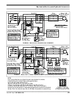
ELECTRICAL WIRING

1. Connect electrical wiring per Figures 18-27

.

Be

sure to use the correct wiring diagram for the power
provided and the pump assembly ordered. 

2. Install the operation switch per Figure 2.  

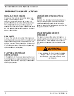
LIP KEEPERS

1.  Using the hoist, slowly lower the leveler platform.

While lowering, make sure the stringers of the
leveler do not impact the pump assembly and other
parts. Also check that the ramp cylinder does not
bottom out.

2. With the leveler flush with the pit wall, mark the

position of  the lip keepers on the front of the frame.
Place strut under leveler.

3. Weld lip keepers in place. See Figure 14B for

recommended lip keeper support for levelers with
inadequate front 
subframes.

UNIT TEST

1.  With the unit fully lowered, activate the power switch

to partially raise the leveler platform. Allow the
leveler to return itself to the lip keepers. Do this
several times to purge the air from the system.

2. Raise the leveler to the full open position and check

for leaks. If leaks do occur, place the leveler on the
Safe-T-Strut and repair leaks.

3. IMPORTANT: With the strut in place (through the lip

hole and on the strut base) test that the leveler does
not lift above the strut top or interfere with the
leveler operation in any way. If the strut does not
remain captured by the lip or if the strut binds in the
lip: consult Rite Hite for the correct strut application.

4. Refill hydraulic fluid tank to indicated level. 

BRACKET ADJUSTMENTS

1. Lower leveler to below dock end load position. If

ramp cylinder bottoms out, adjust pit floor bracket
toward front of pit one set of holes.

2. Raise leveler to highest position. Insure toe guards

do not come out of pit. 

3. Weld the ramp platform bracket securely in place.

This includes welding this bracket to its base and
the stringers of the platform. 

4. Weld the movable portion of the pit floor bracket to

its base. Leave bolts in place.

5. Paint all brackets and welds to control rust.

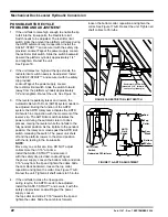
PUMP ADJUSTMENTS

1. Run leveler and adjust properly

a.  Adjust shuttle valve so that leveler platform 

lowers from top to bottom in 14-16 seconds. 
-Adjust the shuttle valve in 1/8-1/4 turn at a time
to speed platform decent 
-Adjust the shuttle valve out 1/8-1/4 turn at a
time to slow platform decent

2. Lip control adjustment

a.  Adjust the sequence valve 

IN

1/4 turn at a time

to slow lip kick at the top of the cycle and stop
lip kick at below dock start up.

b.  Adjust the sequence valve 

OUT

1/4 turn at a

time to speed lip kick at the top of the cycle. Be
careful not to create a lip kick situation at a
below dock start up.

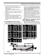
AUTOMATIC RETURN TO DOCK
(ARTD)
GENERAL

The ARTD limit switch assembly automatically turns the
hydraulic power unit on and off to recycle the leveler
from below dock level to dock level, provided the lip has
been fully extended.  A recycle actuator with a rotary
cam assembly moves forward and backward with the
extension and retraction of the lip cylinder. The cylinder
rod moves forward (out) to extend the lip, and backward
(in) to retract the lip.
See Figure 17.

ARTD OPERATION

When the RAISE button is pressed and the ramp
cylinder has fully extended, the lip cylinder rod extends.
The roller of the ARTD limit switch contacts the cam
block, causing the cam to rotate into its “Cylinder
Extend” position. After the cam block passes beyond the
end of the roller plunger limit switch, the cam returns to
its “Cylinder Retract” position. When the lip lowers
toward the pendant position, the lip cylinder retracts,
moving the cam assembly backward. The cam block
contacts the roller of the limit switch, closing the switch.
The power unit is activated, raising the leveler. As soon
as the lip has lowered to the fully pendant position, the
cam block moves past the roller of the limit switch,
which opens the switch and stops the hydraulic power
unit. The leveler returns to the stored position with the
pendant lip lowering into the lip supports. See Figure 17.
The restrictor limit switch prevents the leveler from
raising too high. See Figure 16.

Summary of Contents for Mechanical Dock Leveler Hydraulic Conversion

Page 1: ...Mechanical Dock Leveler Hydraulic Conversion Installation Owner s Manual Rite Hite Print Shop Pub 1147 Rev 7 SEPTEMBER 2004 AFTERMARKET CORPORATION...

Page 2: ...to lock in movable rear hinge if necessary 6 Electrical Cord Conduit Tools Needed 1 Steel hawg magnetic drill or similar drill 2 1 25 bit for magnetic drill 3 Hammer drill 4 Welder Grinder Torch 5 Mi...

Page 3: ...ation does not recommend any particular lockout device but recommends the utilization of an OSHA approved device refer to OSHA regulation 1910 147 RITE HITE Corporation also recommends the review and...

Page 4: ...orm Lip Cylinder Lug Bracket Ramp Clevis Platform Rear Ramp Hinge Pin Lip Lug Lip Keepers Front Bracket Pit Floor MECHANICAL COMPONENTS Subframe Rear Front Rear ELECTRICAL COMPONENTS Rear HYDRAULIC CO...

Page 5: ...Hydraulic oil can be added to the system by removing the cap and pouring oil into the reservoir NOTE When adding oil use only MIL H 5606 SAFETY STOP SYSTEM The hydraulic system has an emergency flow c...

Page 6: ...oncrete in the position for the unit to be capable of conversion PLATFORM CENTERLINE OBSTRUCTIONS If the platform of the leveler has any structural reinforcements or supports between the center string...

Page 7: ...00 lbs WARNING Always use safe work habits This kit includes a maintenance strut Always use this maintenance strut when working under the leveler WARNING Be sure to follow these Caution notes when ins...

Page 8: ...8 Pub 1147 Rev 7 SEPTEMBER 2004 Mechanical Dock Leveler Hydraulic Conversion ELECTRICAL INSTALLATION DETAILS FIGURE 2...

Page 9: ...late Insure the structural integrity of the leveler Make sure the leveler will have at least five more years of useful life after the conversion is complete IMPORTANT Make sure rear hinge of leveler i...

Page 10: ...ng with electrical or electronic controls make sure that the power source has been locked out and tagged according to OSHA regulations 1910 147 and approved electrical codes Barricade work area Post s...

Page 11: ...the method for installing the base depending on the type of front sub frame and the support that will be needed to transfer all loading directly to the pit floor concrete IMPORTANT OBSERVE ALL SAFETY...

Page 12: ...s lip stop bolts etc See Figure 4 2 Position the strut base so the hole is parallel to the front of the leveler and the chamfered edge is against the front frame 3 Shim under the front sub frame at th...

Page 13: ...eight 5 Locate the strut base with extension within 12 of the centerline of the leveler so that it does not interfere with the board operation Before beginning installation check for potential clearan...

Page 14: ...e within 12 of the centerline of the leveler so that it does not interfere with the board operation Before beginning installation check for potential clearance problems with lip lugs header bridge bar...

Page 15: ...er frame near the strut base 4 Connect the free end of the strut chain to the frame anchor loop See Figure 10 FIGURE 8 LIP HOLE LOCATION FIGURE 9 STRUT CUT TO LENGTH LIP INSTRUCTIONS 1 Locate and dril...

Page 16: ...place to the stringers The bracket should open toward the front of the leveler Insure the bracket is square to the leveler deck so the hydraulic cylinder stays on the center line of the leveler 4 Cut...

Page 17: ...nge to position the pit floor bracket See Figure 12 Draw a line on the pit floor parallel to the hinge at this position This dimension is critical to make sure the ramp cylinder does not bottom out on...

Page 18: ...fuse into adapter of ramp cylinder Fasten securely 5 Install hoses between the pump and the ramp and lip cylinders The small hose should be connected to the lip cylinder and the larger hose should get...

Page 19: ...s base Leave bolts in place 5 Paint all brackets and welds to control rust PUMP ADJUSTMENTS 1 Run leveler and adjust properly a Adjust shuttle valve so that leveler platform lowers from top to bottom...

Page 20: ...20 Pub 1147 Rev 7 SEPTEMBER 2004 Mechanical Dock Leveler Hydraulic Conversion FIGURE 14 QUICK CLEAN FRAME MODIFICATIONS...

Page 21: ...Pub 1147 Rev 7 SEPTEMBER 2004 21 Mechanical Dock Leveler Hydraulic Conversion LIP KEEPER SUPPORT FOR LEVELERS WITH INADEQUATE FRONT SUSPENSION FIGURE 15...

Page 22: ...tch activates the power unit during the automatic return to dock process raising the leveler while the lip falls to the fully pendant position As the lip falls to the pendant position the rotary cam m...

Page 23: ...Rev 7 SEPTEMBER 2004 23 Mechanical Dock Leveler Hydraulic Conversion Limit Switch Cam Block Top Collar Bottom Collar Front Header 1 16 Between Center of Switch and Edge of Cam Block FIGURE 17B ARTD AD...

Page 24: ...termittent Duty Thermally Protected With Automatic Reset L2 1L1 Optional Raise Raise ARTD SOLID STATE LEVELER CONTROL MODULE Door Jumper Is Standard Remove Jumper If Optional Overhead Door ITC ITL Is...

Page 25: ...e Typ 2 Places Transformer Secondary Fusing 0 5 Amp 250V 3 AG Slow Blow Optional Door Interlock Limit Switch By Others IMPORTANT Motor Lead Connections Wire Termination Wire Nut Or Equal Device 50 VA...

Page 26: ...0 5 Amp 250V 3 AG Slow Blow Optional Door Interlock Limit Switch By Others LS1 N O H C Restrictor Sw LS2 N O ARTD Limit Sw Motor 1 HP 3450 RPM 380V 3 Ph 50 Hz Use Min 12 Gage 60 75 C Copper Wire 100...

Page 27: ...5 Amp 250V 3 AG Slow Blow Optional Door Interlock Limit Switch By Others LS1 N O H C Restrictor Sw LS2 N O ARTD Limit Sw Motor 1 HP 3450 RPM 480V 3 Ph 50 60 Hz Use Min 12 Gage 60 75 C Copper Wire 100...

Page 28: ...5 Amp 250V MDL Dual Element Type Optional Door Interlock Limit Switch By Others LS1 N O H C Restrictor Sw LS2 N O ARTD Limit Sw Motor 1 HP 3450 RPM 575V 3 Ph 50 60 Hz Motor Lead Connections Wire Term...

Page 29: ...ltage Amps 120 Volt 1 Phase 110 14 115 7 to 14 208 Volt 1 Phase 200 7 205 4 to 7 230 Volt 3 Phase 220 5 5 220 3 8 to 5 5 460 Volt 3 Phase 440 3 2 440 1 9 to 3 2 Motor Single Phase Single Phase Power U...

Page 30: ...leveler DO NOT operate leveler until truck trailer is parked against the dock bumpers and the truck trailer has been secured NEVER attempt to lift the lip or hold the lip out by hand Serious personal...

Page 31: ...lip is on the truck trailer and the truck pulls out the leveler will move to its lowest position and the lip will begin to lower As the lip drops toward the pendant position the ARTD system automatic...

Page 32: ...r and the truck pulls out the leveler will move to its lowest position and the lip will begin to lower As the lip drops toward the pendant position the ARTD system automatically returns the leveler to...

Page 33: ...base 3 Shut off power at the disconnect switch and lockout tagout according to OSHA regulations 4 Remove all debris from the leveler and pit Be sure the hinge section of the lip and platform is clean...

Page 34: ...s Locknut Cap Adjustment Screw Shuttle Valve Body Locknut Seal O Rings Cap Sequence Valve Adjustment Screw Viewed From Tank End System Relief Valve 1 Leveler must be adjusted to lower from full raised...

Page 35: ...turning valve body or adjustment screw 5 Reinstall O ring and protective cap and tighten cap 6 Re test the unit several times to verify the setting 7 If the lip begins to extend at any time before the...

Page 36: ...3 1 2 x 16 S A 5 And 6 Long 3 1 2 GPM 8 And 10 Long 5 GPM Lip Cylinder 1 1 2 x 6 S A Suctin Filter M Motor 3450 RPM Pump Check Valve Orifice Plug Orifice Plug Pilot To Open Check Valve Pilot To Close...

Page 37: ...Pub 1147 Rev 7 SEPTEMBER 2004 37 Mechanical Dock Leveler Hydraulic Conversion OPTIONAL EQUIPMENT DOOR INTERLOCK FIGURE 38 FIGURE 39...

Page 38: ...fitting the bottom of the SAFE T STRUTTM base When working with electrical or electronic controls make sure that the power source has been locked out and tagged according to OSHA regulations and appr...

Page 39: ...t all wires are correctly and solidly connected in the control box motor junction box and pit wall junction box g The overhead door interconnect g With overhead door ITC Verify has failed that limit s...

Page 40: ...ARTD cam power is turned on damaged b The ARTD system has failed b Verify that ARTD and restrictor limit switches are functional Type 2 Control Box Verify that the limit switches are wired to terminal...

Page 41: ...s fully or partially extended a Debris on lip hinge a Remove dirt debris and corrosion from the lip hinge spools b Lack of lubrication b Without grease fittings Lubricate the hinge spools with SAE30 o...

Page 42: ...lowly a Weight on top of platform a Remove weight from platform b Hydraulic fluid level is low b Check oil level in tank Refill if there is less than 3 1 2 of oil in the tank when the unit is held ope...

Page 43: ...ot applicable condition Type 2 Control Box Push RESET button to clear faults c There is a faulty wiring connection c Verify that all wires are correctly and solidly connected in the control box motor...

Page 44: ...e out fault b The pushbutton and or contact block b Type 2 Control Box Replace does not function properly or is stuck pushbutton and or contact block c The ARTD system has failed c Verify that ARTD an...

Page 45: ...JIC M 6728 6728 5 1 FTG ELB 90 4 SAE M 4 JIC M 16920 16920 16920 16920 6 1 FTG ELB 90 6 SAE M 6 JIC M 55267 55267 55267 55267 7 1 FTG ELB 45 4 JIC SWF 4 SAE M 100363 100363 100363 100363 8 1 FTG ELB...

Page 46: ...46 Pub 1147 Rev 7 SEPTEMBER 2004 Mechanical Dock Leveler Hydraulic Conversion ARTD ASSEMBLY...

Page 47: ...102640 11 1 Limit Switch Restrictor 100135 12 2 Screw Round Head 8 32 x 1 3 4 lg 100136 13 2 Washer External Tooth 8 51760 14 4 Washer Flat 8 51736 15 2 Nut 8 32 51538 16 2 Shaft Collar 68163 17 2 Fla...

Page 48: ...103163 2 1 Enclosure 65849 3 1 Switch Plunger OP 25A 125 250V AC 17687 4 1 Armored Pushbutton Boot 17688 5 2 Wire Term Ring Type 12 Wire 8 SCR 17690 6 1 Wire Marker 1L1 55821 7 1 Wire Marker T1 55535...

Page 49: ...HMS 8 32 x 1 1 2 Lg ZP 58181 6 2 Washer Ext Tooth 8 ZP 51839 7 1 Ground Lug and Sticker 55902 8 1 Pushbutton Black IEC 65887 9 2 Contact Block N O IEC 65890 10 1 Corrosion Retard Pad 55561 11 1 Drawin...

Page 50: ...2 100222 100222 100222 7 1 Terminal Block 16848 16848 16848 16848 8 1 Contactor 65911 65911 65911 65911 9 1 Overload Relay 65912 65912 65912 65912 10 1 Corrosion Retard Pad 55561 55561 55561 55561 11...

Page 51: ...0 5 1 Ground Lug and Sticker 55902 55902 55902 55902 6 2 Panel Control Box 100222 100222 100222 100222 7 1 Terminal Block 114 369 114 369 114 369 114 369 8 1 Contactor 65911 65911 65911 65911 9 1 Over...

Page 52: ...52 Pub 1147 Rev 7 SEPTEMBER 2004 Mechanical Dock Leveler Hydraulic Conversion...

Page 53: ...rut Kit 1 1 103967 Safe T Strut 63 long 1 2 51100 Anchor Loop 25 wire dia 1 3 16182 Chain assembly 1 4 59387 Base 4 25 Safe T Strut 1 5 103349 Extension Base 1 6 103495 Competitive Base support angle...

Page 54: ...54 Pub 1147 Rev 7 SEPTEMBER 2004 Mechanical Dock Leveler Hydraulic Conversion MECHANICAL PARTS 8 9 10A 2 3 4 1 11 6 7 5 10B...

Page 55: ...4 590 3 1 Toe Guard 8 Leveler RH 1707 526 4 1 Toe Guard 8 Leveler LH 1708 5 2 Lip Keepers Hydraulic 2175 669 6 1 Toe Guard 10 Leveler RH 1727 7 1 Clevis Pit Floor with Base 18241 8 1 Lip Cylinder Base...

Page 56: ...this warranty RITE HITECorporation will remedy such defects by repairing or replacing any defective equipment or parts bearing all of the costs for parts labor and transportation This shall be the ex...

Reviews: