Pub. 1147 - Rev. 7 SEPTEMBER 2004
17
Mechanical Dock Leveler Hydraulic Conversion
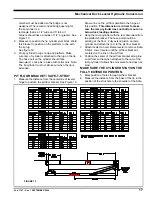
member must be added so the bridge is not
weakened. The recommended bridge opening for
the lip cylinder is a
rectangle that is 4-1/2” wide and 5” tall. All
corners should have a radius of 1/2” or greater. See
Figure 13.
2. Measure to position the lip cylinder pivot block. Weld
this bracket in position on the platform, in line with
the lip lug.
See figure 12
.
3. Pin lip cylinder to lugs on lip and platform. Make
sure ram of cylinder is attached to the lug on the lip.
The hose port on the cylinder should face
downward. Lock pins in place with cotter pins. Note:
The lip cylinder must not stroke out when the lip is
extended.
PIT FLOOR BRACKET / SAFE-T-STRUT
1. Measure the distance from the centerline of leveler
hinge to position the pit floor bracket. See Figure 12
.
Draw a line on the pit floor parallel to the hinge at
this position.
This dimension is critical to make
sure the ramp cylinder does not bottom out on a
below dock loading situation.
2. Hang the ramp cylinder with the ram downward from
the platform bracket. The hose port should be
pointing at the floor. Fully extend piston on ramp
cylinder and attach the ram to the pit floor bracket.
3. Attach leveler to hoist. Raise leveler to remove Safe-
T-Strut. Lower leveler until the pit floor bracket is
centered on the line on the pit floor.
4. Position the center of the pit floor bracket along line
on pit floor so that when attached to the ram of the
ramp cylinder it allows free movement and does not
bind.
MAKE SURE THE CYLINDER STAYS IN THE
FULLY EXTENDED POSITION.
5. Mark position of holes through pit floor bracket.
6. Measure the distance from the base of the lip in the
position of the strut hole to the shoulder of the Safe-
FIGURE 12


