16
Pub. 1147 - Rev. 7 SEPTEMBER 2004
Mechanical Dock Leveler Hydraulic Conversion
CUT AWAY ALL MECHANICAL HARDWARE
1. Relieve tension on all springs and hardware. With
all loads removed, torch away all mechanical parts
from the leveler that move the platform or the lip.
Parts that typically need to be cutaway are
Hydracheck
®
brackets, lifter cams, lip lugs, lifter arm
supports, and safety legs. Grind necessary areas to
eliminate appearance concerns and allow for a
smooth surface for conversion kit to be mounted.
RAMP PLATFORM BRACKET PLACEMENT
(CENTER CHANNEL MUST BE LOCALLY
REMOVED FOR SERCO LEVELERS)
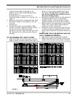
1. Measure from the rear hinge to position the ramp
platform clevis bracket. See figure 12 for
dimensions.
2. Trim the length of the center bracket assembly to
match the dimension from outside of stringer to
outside of stringer on the center bay.
3. Tack weld the bracket in place to the stringers. The
bracket should open toward the front of the leveler .
Insure the bracket is square to the leveler deck so
the hydraulic cylinder stays on the center line of the
leveler..
4. Cut the 3/8” thick flat plate to fit (vertical) between
the stringers and match the stringer shape as
closely as possible.
5. Tack weld the flat plate in place tightly against the
rear side of the first bracket and perpendicular to the
stingers.
6. Recheck dimensions to Figure 12.
7. Weld securely in place to the stringers and weld the
brackets securely together.
8. It may be necessary to cut a hole in one stringer to
install the pin into the cylinder.
LIP CYLINDER AND BRACKETS
1. Measure to position the lip cylinder lug. See figure
12 for dimensions. Weld this lug in position on the lip
next to the spool. It may be necessary to install a
bridge in the header for the lip cylinder. If a bridge
is already present, center lip cylinder lug on bridge
opening. If the bridge must be cut, a reinforcing
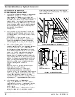
FIGURE 10 (CHAIN INSTALLATION)
12.00 REF.
Chain Assy.
FIGURE 11 (DECAL INSTALLATION)


