24
Pub. 1147 - Rev. 7 SEPTEMBER 2004
Mechanical Dock Leveler Hydraulic Conversion
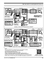
TYPE 1 CONTROLS
Branch Circuit
Disconnect
L1
L2
1L1
L2
1L1
L2
T1
T2
Thermal
Overload
G
G
See Electrical
Installation Details Below
60 / 75 C Copper
Wire/100 Ft. Of Run
20 Amp. Circuit 120V.
15 Amp. Circuit 240V.
Motor – 3/4 HP
2850/3450 RPM
120/240V 1 Ph. 50/60 Hz.
Intermittent Duty
(Thermally Protected
With Automatic Reset)
Pushbutton
Control Box
Type 1
Control Box
TYPE 2 CONTROLS
Branch Circuit
Disconnect
L1
L2
1L1
L2
Restrictor LS
T2
T1
T2
To DOK-LOK
®
Timer Or Controller
For DOK-LOK
®
ITC.
(Optional)
T1
Thermal
Overload
G
G
G
See Electrical
Installation Details Below
60 / 75 C Copper
Wire /100 Ft. Of Run
20 Amp. Circuit 120V.
15 Amp. Circuit 240V.
Motor – 3/4 HP
2850/3450 RPM
120/240V 1 Ph. 50/60 Hz.
Intermittent Duty
(Thermally Protected
With Automatic Reset)
L2
1L1
Optional
“Raise”
Raise
ARTD
SOLID-STATE
LEVELER
CONTROL
MODULE
Door
Jumper Is Standard.
Remove Jumper If
Optional Overhead Door
ITC/ITL Is Installed
Reset
ARTD LS
1
2
4
5
6
7
8
9
Overhead Door ITC/ITL
External Reset
Type 2
Control Box
NOTES:
From Customer Main Power And Safety Protection Device 120/240V 1 Ph. 50/60 Hz.
(Fused Disconnect Supplied By Others)
(Must Use Either Dual Element Fuse Or Inverse Time Circuit Breaker
At Branch Circuit Disconnect.)
One Leveler Per Overload Protection Device.
[Ref. N.E.C. 1999 Para. 430-110 (C) ] Consult Local Code.
A Branch Circuit Disconnect Shall Be Located No More Than 50 Feet From The
Control Box And Must Be Visible. [Ref. N.E.C. 1999 Para. 430-102 (A) And Article 100.]
P1 P2 T3 T8 T2 T4
T1
T2
T5
120
VAC
Motor Wiring
P1 P2 T3 T8 T2
T1
T2
240
VAC
T4 T5
WIRING DIAGRAMS AND SCHEMATICS
FIGURE 18 - TYPE 1 STANDARD ELECTRICAL SCHEMATIC
FIGURE 19 - TYPE 2 STANDARD ELECTRICAL SCHEMATIC


