www.rinnai.it 47
DIP SWITCH SETTING
The boiler PCB is provided with a protection cover that must be removed pushing the clip in the upper part to
reach the connectors. The PCB surface is coated with a silicon rubber to protect the circuits from electric
currents, humidity and dust and guarantee safety and long service life.
Always unplug the boiler when you operate on the PCB: switching off the appliance through the remote
controller is not enough.
Two dip switches blocks are located on the top right part of the PCB: SW1 (left side) and SW2 (right side).
Each dip switch has a specific meaning and function and it must be set accurately following the instruction
reported below if a change is needed.
Dip switch meaning
Below the SW1 are located three different coloured leds.
Their meaning is as follow:
ATTENTION:
to make any change of dip switches effective on the SW1, it is necessary to set nr7
& nr8 to ON position before of any other dip switch change. After the modifications to dip switches
nr1÷5 on SW1 turn the switches nr7 & nr8 back to OFF position.
(
the new parameter changed can be verified by using the leds below the SW1
)
ATTENTION:
to make any change effective on dip switches of the SW2 it is necessary to:
1 - set nr6 e nr7 switches to ON;
2 - change the desired switches;
3 - perform the operations;
4 - make sure the switches nr3÷5 are in OFF position (normal combustion);
5 - set switches nr6 & nr7 back to OFF.
NOTE
: the boiler ignores dip switches nr6 & nr7 ON position (and any forced combustion regime)
after two hours they have been activated; the boiler turns back automatically to a normal
combustion regime for safety reasons.
Summary of Contents for Mirai 24
Page 1: ......
Page 2: ...2 www rinnai it ...
Page 11: ...www rinnai it 11 MAIN COMPONENTS ...
Page 12: ...12 www rinnai it MAIN COMPONENTS ...
Page 30: ...30 www rinnai it MAIN COMPONENTS ...
Page 31: ...www rinnai it 31 GENERAL SCHEME AND OPERATION PRINCIPLES ...
Page 38: ...38 www rinnai it INSTALLATION Type C room sealed forced flue application ...
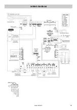
Page 55: ...www rinnai it 55 WIRING DIAGRAM ...
Page 56: ...56 www rinnai it DIAGNOSIS POINT ...
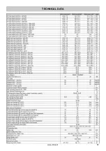
Page 57: ...www rinnai it 57 TECHNICAL DATA ...
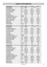
Page 59: ...www rinnai it 59 COMBUSTION PARAMETERS ...
Page 61: ...www rinnai it 61 DATA PLATE ...
Page 62: ...62 www rinnai it CE CERTIFICATE ...
Page 63: ...www rinnai it 63 ...


