36
www.rinnai.it
INSTALLATION
FLUE SYSTEM
The flue system must be installed by authorized personnel only, in accordance with the regulations in force and
the manufacturer’s prescriptions.
It must comply to one of the boiler classes listed on the data plate (located on the boiler side).
Rinnai provides a specific flue system for the boiler and the appliance must not be installed or operate without
the provided flue system.
The flue system must be of a “split type”, Ø80mm separate pipes for air and exhaust
.
Length of the flue system
The exhaust pipe generally operates in a positive pressure condition, for this reason it must be installed
carefully.
The maximum equivalent length is:
type C
type B
(room sealed, forced flue application):
(open chamber, forced flue application):
-
exhaust:
25m -
exhaust:
30m
- air inlet: 5m
Each bend must be considered as an equivalent pipe length that must be deducted from the allowed
extension
:
- 90° bend: 1.5m;
- 45° bend: 0.5m.
Rinnai flue system
Only the Rinnai flue system is approved and suitable for the use with the boiler:
FOT-KS080-001 Extension Kit L=1000mm Ø80mm
FOT-KS080-004 2x45° bend Kit Ø80mm
FOT-KS080-005 1x90° bend Kit Ø80mm
FOT-KS080-007 Horizontal flue kit
(1x90° bend + L=750mm extension pipe + wall flue terminal - Ø80mm)
FOT-KS080-001
FOT-KS080-004
FOT-KS080-005
FOT-KS080-007
Flue system installation
ATTENTION
: prior to assemble the flue system make sure that each part is not damaged: install
intact parts only.
The use of faulty components or an improper installation could result in serious injuries and
material damage
.
All horizontal sections >1.5m need a slope of at least 2.5°-3°
towards the boiler for the exhaust pipe;
outwards for the air inlet pipe.
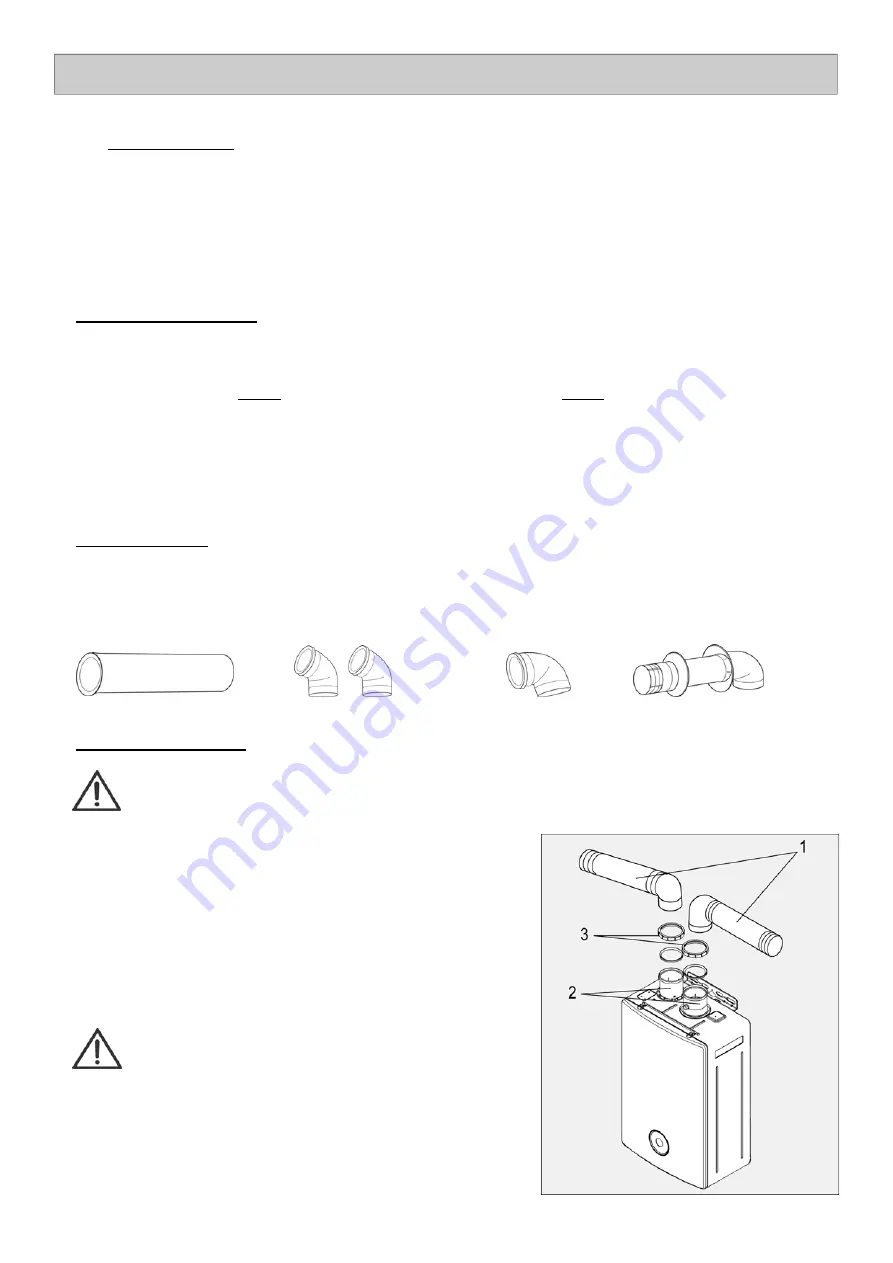
The flue system must be installed according to the picture on the
right:
inserting (
≥
40mm) the pipe (1) in the appropriate location (2),
fastening the connection seal and making sure that there are no
leakage
s
.
ATTENTION
:
if the total equivalent length of the flue system (air inlet +
exhaust) exceeds 15m, the SW1 dip switch nr5 of the PCB
must be changed;
if the inlet air is from indoor room, the SW2 dip switch nr8
of the PCB must be changed.
To make the new setting effective it is necessary to follow
the procedure described in the PCB “Dip Switch setting”
section - Maintenance part of the manual.
Summary of Contents for Mirai 24
Page 1: ......
Page 2: ...2 www rinnai it ...
Page 11: ...www rinnai it 11 MAIN COMPONENTS ...
Page 12: ...12 www rinnai it MAIN COMPONENTS ...
Page 30: ...30 www rinnai it MAIN COMPONENTS ...
Page 31: ...www rinnai it 31 GENERAL SCHEME AND OPERATION PRINCIPLES ...
Page 38: ...38 www rinnai it INSTALLATION Type C room sealed forced flue application ...
Page 55: ...www rinnai it 55 WIRING DIAGRAM ...
Page 56: ...56 www rinnai it DIAGNOSIS POINT ...
Page 57: ...www rinnai it 57 TECHNICAL DATA ...
Page 59: ...www rinnai it 59 COMBUSTION PARAMETERS ...
Page 61: ...www rinnai it 61 DATA PLATE ...
Page 62: ...62 www rinnai it CE CERTIFICATE ...
Page 63: ...www rinnai it 63 ...

