Repairs | 9
User and maintenance manual
133 / 148
Removing defective cell
Fig. 78:
Drive switch and main switch
1 Main switch
2 Drive switch
3 Drive switch indicator
Fig. 79:
Cells in side box
1 Sense boards
2 Side box screws
3 Side box
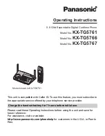
Fig. 80:
Disconnecting cells
1 Cell connector
2 Sense board
3 Load cable
4 Cell connector
5 Brace screws
6 Main power cable
7 Brace
2
1
3
1
2
2
3
3
3
2
6
7
1
4
5