39
INSTALLER
T (°C)
R (
Ω
)
T (°C)
R (
Ω
)
T (°C)
R (
Ω
)
-50
43907
-5
3600
40
574.7
-45
31840
0
2857
45
482.8
-40
23374
5
2284
50
407.4
-35
17359
10
1840
55
345.3
-30
13034
15
1492
60
293.8
-25
9889
20
1218
65
250.8
-20
7578
25
1000
70
214.9
-15
5861
30
826.8
75
184.8
-10
4574
35
687.5
2 .16
Outdoor sensor connections
Correct positioning of the outside temperature sensor is essential to proper indoor climate control.
The sensor must be installed outside the building to be heated, about 2/3 of the way up a NORTH or NORTH-WEST facing
wall, well clear of any flues, doors, windows and out of direct sunlight.
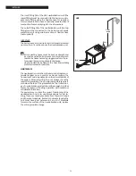
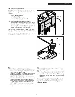
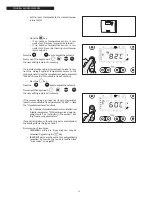
Fixing the outdoor temperature sensor to the wall
− Unscrew (anti-clockwise) the cover from the
sensor casing to access the sensor terminals and
fixing holes.
− Use the sensor casing as a template to mark the
drilling points on the wall.
− Remove the sensor casing and drill 5x25 holes for
the expansion plugs.
− Fix the sensor casing to the wall using the two
expansion plugs provided.
− Unscrew the nut on the cable guide and insert a
two core cable (with cross section between 0.5
and 1mm2, not supplied) to connect the sensor
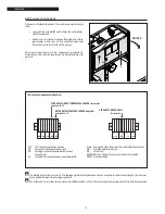
to terminals 20 and 21 in the boiler (see diagram
on previous page).
− Connect the two wires of the cable to the sensor
terminals. Polarity is irrelevant.
− Tighten the nut on the cable guide and fit the
cover on the sensor casing.
9
Position the outdoor temperature sensor on a smooth area of wall. Prepare a smooth contact area for the sensor
casing if the wall is made from exposed brick or other rough material.
9
Avoid joins in the cable between the outdoor temperature sensor and the control panel. If different cable lengths
have to be joined, make sure that the joins are sealed and adequately protected.
9
If cable ducts are used to route the sensor connection cable, keep these well clear of any power cables (230Vac).
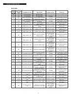
Correspondence table
Measured temperature (°C) – Resistance of outdoor temperature sensor (
Ω
).

