45
8.5 ELECTRICAL CHECKS
Any electrical checks must be carried out by a suitably qualified
person.
8.5.1 EARTH CONTINUITY TEST
Isolate the appliance from the electrical supply, and using a
suitable multi-meter carry out a resistance test. Connect test
leads between an appliance earth point and the earth wire of
the appliance supply cable. The resistance should be less than
1 OHM. If the resistance is greater than 1 OHM check all earth
wires and connectors for continuity and integrity.
8.5.2 SHORT CIRCUIT CHECK
Isolate the appliance from the electrical supply, and using a
suitable multi-meter, carry out a short circuit test between the
Live & Neutral connections at the appliance terminal strip.
Repeat above test on the Live & Earth connections at the
appliance terminal strip.
NOTE
Should it be found that the fuse has failed but no fault is
indicated, a detailed continuity check will be required to trace
the fault. A visual inspection of components may also assist in
locating the fault.
8.5.3 POLARITY CHECK
With the appliance connected to the electrical supply and using
a suitable multimeter, carry out the following voltage tests:
• connect test leads between the Live & Neutral connections
at the appliance terminal strip. The meter should read
approximately 230V ac. If so proceed to next stage. If not,
see section 8.6.
• connect test leads between the Live & Earth connections at the
appliance terminal strip. The meter should read approximately
230V ac. If so proceed to next stage. If not, see section 8.6.
• connect test leads between the Neutral & Earth connections
at the appliance terminal strip. The meter should read
approximately 0 – 15Vac. If so polarity is correct. If not, see
section 8.6.
8.5.4 REVERSED POLARITY OR SUPPLY FAULT
Repeat the above tests at the appliance isolator, if testing
reveals correct polarity and/or supply at the isolator, re-check
wiring and connections between the isolator and the appliance.
If tests on the isolator also reveal reversed polarity or a supply
fault, consult the local electricity supplier for advice.
DISTANCE TO EARTH CHECK
Isolate the appliance from the electrical supply, and using a
suitable multi-meter carry out a resistance test. Connect test
leads between the Live & Earth connections at the appliance
terminal strip. If the meter reads other than infinity there is a
fault that must be isolated, carry out a detailed continuity check
to identify the location of the fault.
These series of checks must be carried out before attempting
any faultfinding procedures on the appliance. On completion
of any task that required the disconnection and re-connection
of any electrical wiring or component, these checks must be
repeated.
8.6 FAULT FINDING
Before attempting any faultfinding, the electrical checks as
detailed in section 8.5 must be carried out. Isolate the appliance
from the electrical supply.
Disconnect any external controls from terminal plug, and insert
a link-wire between the two wires at the ‘TA’ connections of the
8-poles connector.
NOTE:
restore the electrical supply to the boiler and RESET
functionning. The boiler should now function as described
in section 8.2. Should the boiler fail to respond, the internal
fuses and connectors should be checked to ensure integrity
and continuity.
8.7 APPLIANCE STATUS AND FAULT CODES
When the boiler detects a temporary fault condition, the
appropriate code is shown. If/when the fault is final, the pump
will perform 30 to 60-second post circulation (depending on the
error code) and fault code will be displayed. For combustion
fault, FAN can also post vent up to 5min if required.
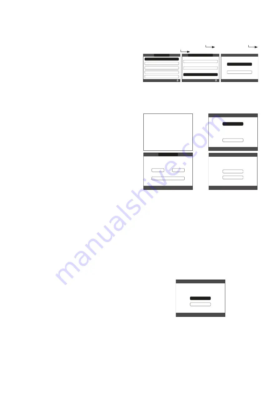
8.8 REC10CH SYSTEM RESET
Warning! – This operation must only be carried out by
qualified personnel!
If required, the system configuration can be reset back to the
factory default configuration; however care needs to be taken
in order to carry out a successful reset:
- access to menu TECHNICAL
INSTALLATION
SYSTEM RESET
CONFIRM or CANCEL
CANCEL
CONFIRM
ZONES MANAGER
SENSOR CALIBRATION
SYSTEM RESET
INSTALLER
INSTALLATION
RANGE RATED
WEATHER COMPENSATION
PARAMETERS
CALIBRATION
INSTALLATION
INSTALLER
TECHNICAL
-
the UI screen will display the firmware version – press any
key to continue
- select language (ENGLISH)
- enter the time and date
- select MASTER
-
select configuration type: NEW or
MAIN PCB (see below)
ITALIANO
ENGLISH
MULTI ZONE CONTROLLER
REC10 V01.26
PRESS ANY KEY
TO CONTINUE
SELECT THE TYPE
OF CONFIGURATION
NEW
FROM AKM
MAIN PCB
12
17
:
ENTER TIME AND DATE
TIME & DATE
USE THE ARROWS TO MODIFY
18 / 11 / 2013
8.8.1 BOILER CONFIGURATION
The BOILER menu allows you to change the hydraulic confi-
guration without necessarily having to go through a SYSTEM
RESET operation.
The HYDRAULIC CONFIG parameter can assume values
between 0 and 4 with the following meaning:
0 = System boiler (heating only boiler)
1 = Combination boiler (instantaneous) with flowswitch
2 = Combination boiler (instantaneous) with flowmeter (Flux
meter)
3 = System boiler & cylinder with probe
4 = System boiler & cylinder with thermostat.
8.8.2 CONFIGURATION FROM AKM PCB
- S
elect configuration type:
MAIN PCB
- The REC10CH will use the information/settings stored on
the AKM PCB to configure the appliance
SELECT THE TYPE
OF CONFIGURATION
NEW
MAIN PCB
8.8.3 NEW CONFIGURATION
- S
elect configuration type:
NEW
- Select location of REC10CH:
ON BOARD
- Select PLANT type:
CH ONLY
–
INSTANTANEOUS
–
HW
(STORAGE TANK)
(see below)


