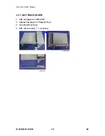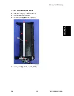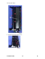
Scanner Unit (only for MF Models)
SM
3-11
M199/M200/M203/M204
Rep
lacemen
t
a
nd A
d
jus
tm
e
nt
3.4 SCANNER UNIT (ONLY FOR MF MODELS)
3.4.1 SCANNER UNIT
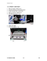
1. Rear cover (page 3-6 "Rear Cover")
2. Controller box cover (page 3-63 "Controller Board")
3. Remove the left stand cover [A] and right stand cover [B]. (hook × 1 each)
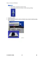
4. Disconnect the two flat cables [C] with the ferrite core [D] (
×2, 2 hooks).
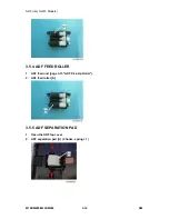
5. Disconnect the three harnesses and ground wire from the left stand. (
× 3,
× 1)
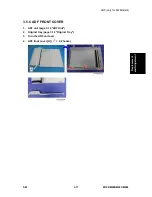
6. Open the top cover and remove the stepped screw [E].
Summary of Contents for M199
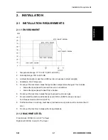
Page 1: ...M199 M200 M203 M204 SERVICE MANUAL ...
Page 14: ...PRODUCT INFORMATION REVISION HISTORY Page Date Added Updated New None ...
Page 23: ...INSTALLATION ...
Page 27: ...REPLACEMENT AND ADJUSTMENT REVISION HISTORY Page Date Added Updated New None ...
Page 49: ...ADF only for MF Models M199 M200 M203 M204 3 22 SM 5 Document sensor C 4 hooks 1 ...
Page 68: ...Image Transfer SM 3 41 M199 M200 M203 M204 Replacement and Adjustment 7 ITB contact motor D 2 ...
Page 107: ...Electrical Components M199 M200 M203 M204 3 80 SM 7 PSU E 4 ...
Page 115: ...SYSTEM MAINTENANCE REFERENCE REVISION HISTORY Page Date Added Updated New None ...
Page 146: ...TROUBLESHOOTING REVISION HISTORY Page Date Added Updated New None ...
Page 174: ...ENVIRONMENTAL CONSERVATION REVISION HISTORY Page Date Added Updated New None ...
Page 180: ...M199 M200 M203 M204 SERVICE MANUAL APPENDICES ...
Page 182: ...APPENDIX SPECIFICATIONS REVISION HISTORY Page Date Added Updated New None ...
Page 200: ...APPENDICES PREVENTIVE MAINTENANCE REVISION HISTORY Page Date Added Updated New None ...
Page 207: ...PAPER FEED UNIT TK1010 G849 REVISION HISTORY Page Date Added Updated New None ...

