Adjusting Copy Image Area
SM 4-9
M052/M053/M054
R
e
p
la
cem
e
n
t
and
Adjus
tm
e
nt
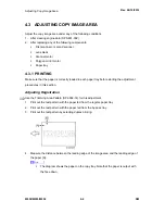
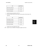
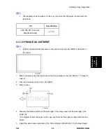
The diagrams show the paper on the copy tray. Note that the paper is output with the
face down.
SP
Specification
SP4-008-001 (Sub Scan
Magnification Adj)
± 1.0%
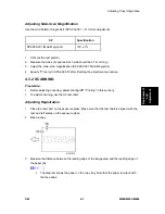
4.3.3 DF IMAGE ADJUSTMENT
Perform the adjustment procedure in this section only when the ARDF is installed on
the copier.
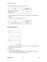
1. Make a temporary test chart as shown in the above diagram. Use the “A4/8.5 x 11" paper to
make it.
2. Place the temporary test chart on the ARDF.
3. Make a copy.
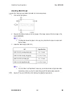
4. Measure the distance between the side edge of the image area and the side edge of the
paper [A].
(The diagram shows the paper on the copy tray. Note that the paper is output with the face
down.)
5. Adjust the side-to-side registration (S to S/Front Regist: SP6-006-001, S to S/Rear Regist:
Summary of Contents for M052
Page 1: ...M052 M053 M054 SERVICE MANUAL ...
Page 15: ......
Page 20: ...PRODUCT INFORMATION REVISION HISTORY Page Date Added Updated New None ...
Page 21: ......
Page 31: ......
Page 76: ......
Page 77: ...PREVENTIVE MAINTENANCE REVISION HISTORY Page Date Added Updated New None ...
Page 78: ......
Page 82: ......
Page 210: ...1 Bin Tray Unit M052 M053 M054 4 128 SM 10 Remove two screws A ...
Page 214: ......
Page 216: ......
Page 426: ......
Page 466: ......
Page 467: ...ENERGY SAVING REVISION HISTORY Page Date Added Updated New None ...
Page 468: ......
Page 474: ...M052 M053 M054 SERVICE MANUAL APPENDICES ...
Page 475: ......
Page 477: ......
Page 479: ......
Page 495: ......
Page 496: ...APPENDIX PREVENTIVE MAINTENANCE TABLES REVISION HISTORY Page Date Added Updated New None ...
Page 497: ......
Page 501: ...M381 FAX OPTION TYPE SP5200 REVISION HISTORY Page Date Added Updated New None ...
Page 502: ......
Page 506: ......
Page 649: ......
Page 651: ......
Page 653: ......

