Adjusting Copy Image Area
M052/M053/M054 4-4
SM
4.3 ADJUSTING COPY IMAGE AREA
Adjust the copy image area under any of the following conditions:
1. After clearing engine data (SP5-801-002).
2. After replacing any of the following components:
First scanner or second scanner
Lens
block
Scanner
motor
Polygon mirror motor
Paper
tray
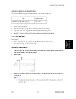
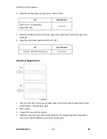
4.3.1 PRINTING
Make sure that the paper is correctly loaded in each paper tray before starting the adjustment
procedures in this section.
Adjusting Registration
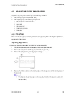
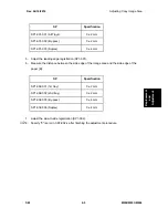
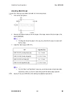
Use the Trimming Area Pattern (SP2-902-14) for this adjustment.
1. Print out the test pattern with the paper fed from the regular paper tray.
2. Print out the test pattern with the paper fed from the by-pass tray.
3. Print out the test pattern by selecting duplex printing.
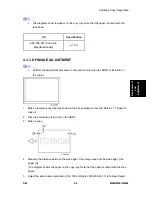
4. Measure the distance between the leading edge of the image area and the leading edge of
the paper [A].
The diagram shows the paper on the copy tray. Note that the paper is output with
the face down.
⇒
Rev. 04/10/2012
Summary of Contents for M052
Page 1: ...M052 M053 M054 SERVICE MANUAL ...
Page 15: ......
Page 20: ...PRODUCT INFORMATION REVISION HISTORY Page Date Added Updated New None ...
Page 21: ......
Page 31: ......
Page 76: ......
Page 77: ...PREVENTIVE MAINTENANCE REVISION HISTORY Page Date Added Updated New None ...
Page 78: ......
Page 82: ......
Page 210: ...1 Bin Tray Unit M052 M053 M054 4 128 SM 10 Remove two screws A ...
Page 214: ......
Page 216: ......
Page 426: ......
Page 466: ......
Page 467: ...ENERGY SAVING REVISION HISTORY Page Date Added Updated New None ...
Page 468: ......
Page 474: ...M052 M053 M054 SERVICE MANUAL APPENDICES ...
Page 475: ......
Page 477: ......
Page 479: ......
Page 495: ......
Page 496: ...APPENDIX PREVENTIVE MAINTENANCE TABLES REVISION HISTORY Page Date Added Updated New None ...
Page 497: ......
Page 501: ...M381 FAX OPTION TYPE SP5200 REVISION HISTORY Page Date Added Updated New None ...
Page 502: ......
Page 506: ......
Page 649: ......
Page 651: ......
Page 653: ......

