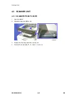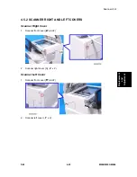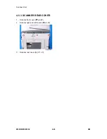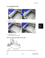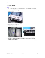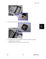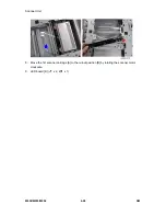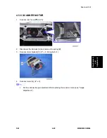
Scanner Unit
M052/M053/M054 4-36
SM
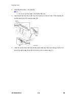
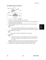
4. Install the drive pulley on the shaft [A].
Do not secure the pulley to the shaft at this time.
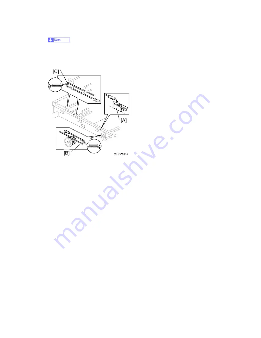
5. Insert the left end into the slit [B]. The end should go via the rear track of the left pulley [C]
and the rear track of the movable pulley [D].
6. Hook the right end onto the front scanner wire bracket [A]. The end should go via the front
track of the right pulley [B] and the front track of the movable pulley [C].
Summary of Contents for M052
Page 1: ...M052 M053 M054 SERVICE MANUAL ...
Page 15: ......
Page 20: ...PRODUCT INFORMATION REVISION HISTORY Page Date Added Updated New None ...
Page 21: ......
Page 31: ......
Page 76: ......
Page 77: ...PREVENTIVE MAINTENANCE REVISION HISTORY Page Date Added Updated New None ...
Page 78: ......
Page 82: ......
Page 210: ...1 Bin Tray Unit M052 M053 M054 4 128 SM 10 Remove two screws A ...
Page 214: ......
Page 216: ......
Page 426: ......
Page 466: ......
Page 467: ...ENERGY SAVING REVISION HISTORY Page Date Added Updated New None ...
Page 468: ......
Page 474: ...M052 M053 M054 SERVICE MANUAL APPENDICES ...
Page 475: ......
Page 477: ......
Page 479: ......
Page 495: ......
Page 496: ...APPENDIX PREVENTIVE MAINTENANCE TABLES REVISION HISTORY Page Date Added Updated New None ...
Page 497: ......
Page 501: ...M381 FAX OPTION TYPE SP5200 REVISION HISTORY Page Date Added Updated New None ...
Page 502: ......
Page 506: ......
Page 649: ......
Page 651: ......
Page 653: ......

