


ELECTRICAL COMPONENT DEFECTS
10 August, 2001
7-18
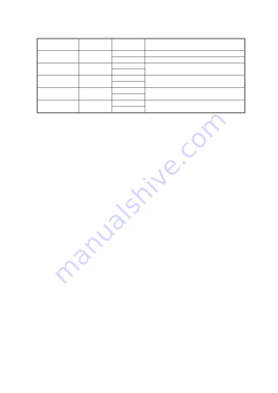
Component
(Symbol)
CN
Condition
Symptom
Open
SC502 will be displayed.
2nd Paper Lift
305-10
(
SBCU)
Shorted
Paper jam will occur during copying.
Open
1st Paper Height
– 1
307-B2
(
SBCU
)
Shorted
The CPU cannot determine the paper near-
end condition properly.
Open
1st Paper Height
– 2
307-B5
(
SBCU
)
Shorted
The CPU cannot determine the paper near-
end condition properly.
Open
2nd Paper Height
– 1
307-B9
(
SBCU
)
Shorted
The CPU cannot determine the paper near-
end condition properly.
Open
2nd Paper Height
– 2
307-B12
(
SBCU
)
Shorted
The CPU cannot determine the paper near-
end condition properly.
NOTE:
An SC condition occurs only when a new PCU is being installed in the
machine. During copying, if the ID sensor fails, the image density will be
changed.