background image

Radio Frequency Systems   

BD210WLP Series Air Dryer User’s Guide 


Page 49 of 101  

100518832 – Rev. B 

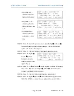
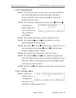
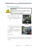
8.10  Setting the Outlet Pressure 

8.10.1  


Locate the outlet pressure regulator on the front of the unit 


8.10.2  


Turn knob until Outlet 

Pressure (

OUTP

reading is at the desired 

setting.   


8.10.3  


Tighten the retaining 

nut to lock value in 

place. 


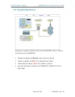
8.11  Connecting to Common Alarm Terminals 


8.11.1  


Wire the Alarm Harness to monitoring device using the table below for 

reference: 


Wire # 

Wire Color 

Function 

Power Fail 

13 

RED 

SHORT 

on Alarm 

Alarm 

16 

BLACK 

Common 

14 

BLACK 

SHORT 

on Alarm 

Alarm 

17 

BLUE 

Common 

15 

BLUE 

OPEN 

on Alarm 

Alarm 

18 

BLACK 


8.11.2  


Connect the Alarm 

Harness to the Alarm Port 

on the back of the 

Dehydrator.  


Summary of Contents for BD210WLP Series

Page 1: ...100518832 Rev B BD210WLP Series Air Dryer User s Guide Models covered BD210WLP BD210WLP V BD212WLP BD212WLP V ...

Page 2: ......

Page 3: ...com 2 Introduction PLEASE READ THIS USER S GUIDE THOROUGHLY AND SAVE FOR FUTURE REFERENCE This User s Guide is provided for the benefit of our customers and contains information and direction specific to the RFS BD210WLP Series Air Dryers Models covered include BD210WLP BD210WLP V BD212WLP and BD212WLP V This guide covers topics including safety specifications installation registration operation t...

Page 4: ...setting Dryer Set Points 36 8 8 Open Panel 48 8 9 Setting the System Pressure 48 8 10 Setting the Outlet Pressure 49 8 11 Connecting to Common Alarm Terminals 49 8 12 Connecting via Web Browser 50 8 13 Using the Status Screen 52 8 14 Using the Setup Screen 54 8 15 Using the Event Alarm Screen 56 8 16 Using the Firmware Screen 57 8 17 Connecting via SNMP 58 9 Testing Your Dryer 59 9 1 Safety Warnin...

Page 5: ...essure Alarm 88 13 9 Can t Create a Low Pressure Alarm 88 13 10 High Humidity 89 13 11 Can t Create a High Humidity Alarm Shutdown 90 13 12 High Duty Cycle Alarm 90 13 13 High Cabinet Temperature Alarm 90 13 14 Inconsistent Heatless Dryer Cycling 91 13 15 Compressor Doesn t Operate 91 13 16 Compressor Won t Build Pressure 92 13 17 Compressor Excessive AMP Draw 92 13 18 High Compressor Last Run Tim...

Page 6: ...will include the symbol as well as a label of WARNING CAUTION or IMPORTANT Please be sure to pay close attention for these warnings and read them as you encounter them WARNING For your safety all the information in this User s Guide must be followed to minimize the risk of electrical shock and prevent property damage or personal injury WARNING Extreme care should be exercised to avoid contact with...

Page 7: ...EVER remove pressure sensing tubes from the Control Board without depressurizing the Air Dryer first or damage to the Control Board will occur CAUTION Incoming power to Dryer must be 15 amp service recommended 110 125 VAC 50 60 Hz for BD210WLP models 208 253 VAC 50 60 Hz 1 Phase for BD212WLP models CAUTION Proper installation maintenance as outlined in this User s Guide is extremely important to e...

Page 8: ...ing routine maintenance as outlined in the Maintaining Your Dryer section will ensure optimal performance over the lifecycle of your Air Dryer CAUTION This Air dryer does not contain an internal Surge Protection Device SPD An SPD is required and must be supplied by the user CAUTION Observe precautions for handling Electrostatic Sensitive Devices IMPORTANT Installation of RFS air dryers is intended...

Page 9: ...r indoor use The BD210WLP Series Air Dryers employ a fully digital operating platform offering the most accurate readings of Dryer variables removable access panel allowing easier access for adjustment and maintenance and ultra quiet compressor with an industry leading maintenance interval 5 2 Key Features LCD display of all operating parameters Solid state microprocessor based circuitry eliminate...

Page 10: ...essor Type Oil less Piston Type Drying Method Heatless Desiccant Optimal Operating Temperature Range 40º 85ºF 5º 30ºC Ambient Unit will go into SHUTDOWN mode if Cabinet Temperature exceeds 120ºF 49ºC Alarms Standard Alarms Complete readings of all critical measurement points individual alarm indication display including SNMP Communication Outlet Connections 3 8 Press to lock Fitting Dimensions 6 7...

Page 11: ...ter from the coalescing filter 5 Heatless Dryer Removes moisture from the compressed air 6 Capacity Control Valve Regulates system pressure and prevents air from bleeding back through the heatless dryer 7 Air Tank Stores compressed dry air 8 Outlet Pressure Regulator Regulates the outlet pressure to the desired outlet condition 9 Humidity Sensor Measures the humidity of the compressed air 10 Syste...

Page 12: ...you remove all jewelry before performing any procedures WARNING Internal surfaces may be hot Use care when coming into contact with internal components as there is a potential for some of these components to become hot when in operation or standby CAUTION Proper installation maintenance as outlined in this User s Guide is extremely important to ensure the reliability and longevity of the equipment...

Page 13: ...yourself with the components and procedures before performing the air Dryer installation 6 2 3 Verify the installation location of the air Dryer 6 2 3 1 Well ventilated and free from abrasive dust or chemicals IMPORTANT Performing procedures not described in this User s Guide or installing components not supplied by RFS is NOT RECOMMENDED AND MAY VOID THE WARRANTY CAUTION Incoming power to Dryer m...

Page 14: ... minimum 15 amp service 6 2 4 Notify the alarm center of the installation and potential for alarms during the process as necessary 6 3 Included Contents 1 BD210WLP Series Air Dryer 1 120 VAC Power Cord BD210WLP models 1 220 VAC Power Cord BD212WLP models 4 Connector Male 1 4 MPT Swivel Elbow 1 Precision Bleed Orifice Fitting 1 Rack Mounting U shaped Bracket BD210WLP V Excluded 2 Rack Mounting Ear ...

Page 15: ...ter remove the Dryer from box and all shipping materials NOTE If ANY SHIPPING DAMAGE is detected file a claim with the shipping company prior to continuing the installation procedures 6 5 2 Open panel latches and remove the top panel NOTE The top panel is equipped with locking latches if a higher level of security is required 6 5 3 Check for loose parts hoses or wiring NOTE If ANY SHIPPING DAMAGE ...

Page 16: ...hilips head screw and pulling the block free NOTE Do not discard shipping block Shipping block must be re inserted in the case of a future event requiring movement of the dryer See section 6 7 6 5 5 Remove the plastic plug from the purge port 6 5 6 Remove the metal plug from the outlet port Install the plug into the included precision bleed orifice fitting and then into the dryer Outlet Port ...

Page 17: ...t installations 6 5 7 1 Extend the drawer slide brackets and separate into two components by pressing down on the black lever and pulling apart 6 5 7 2 Install the smaller of the two slide components on the side panels of the unit by inserting two of the supplied 8 32 x 5 16 screws into the pre threaded holes on each side of the unit Use loctite to secure the screws ...

Page 18: ...ed 10 32 x 3 8 screws on each side Use Loctite to secure the screws 6 5 7 4 Install one of the mounting ear brackets on each side of the U shaped mounting bracket using two 10 32 x 5 8 screws two washers and two 10 32 Nylock nuts NOTE The mounting ears are reversible to accommodate both 19 and 23 racks The mounting ears can be installed in various positions along the depth of the U shaped bracket ...

Page 19: ...nit sway see section 11 3 for ordering information 6 5 7 6 From a supported position lift and slide the unit into the U shaped bracket assembly that is installed in the server rack Take care to align the drawer slide components so that they engage correctly with each other Firmly push the unit until it is fully installed and the drawer slides will lock to prevent accidental separation NOTE The uni...

Page 20: ...llation process for wall mounting a BD210WLP Series dryer The installation components required for wall mounting are NOT INCLUDED with the standard dryer see section 11 3 for ordering information 6 5 8 2 Install a wall mount bracket on each side panel of the unit using two 8 32 x 3 8 screws and two washers Use Loctite to secure the screws 6 5 8 3 Refer to the following hole pattern to locate faste...

Page 21: ...V and BD212WLP V model units All other BD210WLP series dryers MUST be mounted in a horizontal orientation 6 5 9 1 Each BD210WLP V dryer is shipped with a standard vertical wall mount installation kit Section 6 5 9 outlines the general installation process for wall mounting a BD210WLP V dryer 6 5 9 2 Install a wall mount bracket on each side panel of the unit using two 8 32 x 3 8 screws and two was...

Page 22: ...sile pullout strength is 2 000 pounds per anchor 907 kg 6 5 9 5 Ensure that the unit is mounted with the display facing upwards 6 5 10 Verify that the Dryer is powered OFF 6 5 11 Plug AC Power Cord to Dryer 6 5 12 Wire or plug the power cord into 110 125 VAC power outlet for the BD210WLP model 208 253 VAC 1 phase power outlet for the BD212WLP models o Line Black Brown o Neutral White Blue o Ground...

Page 23: ...low through the Outlet Port 6 5 14 Set the System Pressure With Compressor running 6 5 14 1 Pull the Capacity Control Valve knob out 6 5 14 2 Turn the knob until the reading on the pressure gauge is 50 PSI 344 7 KPa 6 5 14 3 Push the knob in to lock Let the Dryer run until the Humidity drops below 2 may take up to 15 minutes Press the RESET button if the Dryer goes into SHUTDOWN mode ...

Page 24: ... the downstream system is pressurized prior to installation of dryer make reasonable attempts to install the dryer while minimizing system depressurization Complete depressurization may result in ambient moisture being introduced into the system which may require extended run time and dryer cycling to reduce or eliminate Ambient moisture in the downstream system may result in high humidity alarms ...

Page 25: ...er the Dryer ON 6 5 20 Set the Outlet Pressure 6 5 20 1 Loosen the retaining nut and turn knob until Outlet Pressure OUTP reading is at the desired setting 6 5 20 2 Tighten the retaining nut to lock the knob in place 6 5 21 Check for air leaks NOTE This is a general procedure that can be applied to any fitting or hose that has air pressure in it DO NOT SOAP TEST THE HUMIDITY SENSOR FITTING DAMAGE ...

Page 26: ...nection If any leaks are detected take steps to seal them off as necessary Tighten the fitting Re connect the hose end Replace the fitting hose component 6 5 22 It is recommended to observe the air dryer for a minimum of 30 minutes 1 hour preferred and or through multiple run and dwell cycles to ensure there are no issues e g humidity flow compressor run time etc which may result in alarms and or ...

Page 27: ...our Dryer 6 7 1 If relocating your dryer to another site of operation or packaging to ship for service perform the following steps prior to movement to ensure your dryer continues to operate optimally 6 7 1 1 Return the shipping block to the compressor assembly by re inserting the block between the compressor brackets and re inserting the 8 32 x screw See section 6 5 4 for reference 6 7 1 2 Remove...

Page 28: ...ry to activate the Limited Warranty on your product Once you register you are eligible to receive free technical support as well as updates concerning your RFS products Register Online at http www AltecAIR com registration html Or by Phone 1 800 521 5351 option 2 Have the following information available Model Serial Company Name Location Name Shipping Address City State Zip Code Contact Name Phone...

Page 29: ...electrical shock It is highly recommended that you remove all jewelry before performing any procedures WARNING Internal surfaces may be hot Use care when coming into contact with internal components as there is a potential for some of these components to become hot when in operation or standby IMPORTANT Performing procedures not described in this User s Guide or installing components not supplied ...

Page 30: ...y Lines to the Dryer 8 2 1 Connect a 3 8 air supply line to the Outlet Port NOTE For all dryers with minimal flow install the Precision Bleed Orifice fitting to maintain a constant flow of air 8 2 2 Power the Dryer ON CAUTION Be careful when removing outlet plugs or connected Air Supply Lines System may be pressurized ...

Page 31: ...ee section 8 4 for detail 8 3 2 Open Top Panel 8 3 3 Pull the ring handle on the air tank until all the air pressure is released 8 3 4 Close Top Panel 8 4 Powering the Dryer ON OFF 8 4 1 POWER Switch Controls the main power to the Dryer CAUTION Incoming power to Dryer must be 15 amp service recommended 110 125 VAC 50 60 Hz for BD210WLP models 208 253 VAC 50 60 Hz 1 Phase for BD212WLP models ...

Page 32: ...information screen on the display When pressed again it will allow the information screens to begin cycling again 8 5 4 Arrow Buttons Used to access navigate and change values in the Set Point Adjust screens 8 5 5 Display Screen Shows the current Dryer readings Will cycle between the following information screens unless the HOLD button has been pressed CAUTION The Display Screen is covered by a cl...

Page 33: ...tes the compressor ran during the last Air Tank pressurization cycle TOTAL Number of hours of compressor run time since the total run time value was manually reset 8 5 5 3 System Status SYS STATUS Signal to determine if the unit is online or in shutdown Running Status of the system ONLINE System is online SHUTDOWN System has been shut down as a result of either a humidity or high cabinet temperatu...

Page 34: ...n 8 6 2 Low Outlet Pressure Alarm Occurs when the Outlet Pressure OUTLET drops below the alarm set point for more than one 1 minute See section 13 8 for troubleshooting information 8 6 3 High Humidity Alarm Occurs when the Humidity level rises above the alarm set point for more than one 1 minute If this alarm is present for one 1 minute or more the air Dryer will go into SHUTDOWN mode to prevent s...

Page 35: ...yer will go into SHUTDOWN mode to prevent damage to the unit See section 13 13 for troubleshooting information 8 6 5 High Compressor Last Run Time Alarm Occurs when the compressor takes longer to pressurize the air tank than the set point for the alarm See section 13 18 for troubleshooting information 8 6 6 Compressor Total Hour Alarm Occurs when the compressor has reached a recommended maintenanc...

Page 36: ...nts is factory programmed with a default value based on typical usage of the air Dryer Many of the set points for Dryer alarms can be modified to levels more closely based upon your specific application NOTE Reference Appendix Section 14 3 for Limits and Defaults 8 7 1 Navigating the Setup Menus 8 7 1 1 From any of the home screens press the Up Arrow Button to access the setup menu screen 8 7 1 2 ...

Page 37: ... Delay 8 7 2 1 The Alarm Delay allows the dryer time to correct out of an alarm condition on its own without signaling an alarm o ON default waits one 1 minute before signaling alarms o OFF Signals alarms immediately 8 7 2 2 From the system setup menu screen press the Up Down Arrow Buttons to navigate between the system setup options to locate SET ALARM DELAY 8 7 2 3 Press the Enter button to ente...

Page 38: ...Total Hours 8 7 4 1 Compressor total hours is the number of compressor runtime hours since startup or the last time the compressor time counter was reset The dryer will display an alarm when this counter has reached 2 000 hours signaling it is the recommended time to perform preventative maintenance When the compressor total hours are reset the counter will return to zero 8 7 4 2 From the system s...

Page 39: ...essor total hours 8 7 5 2 From the system setup menu screen press the Up Down Arrow Buttons to navigate between the system setup options to locate RESET TO FACTORY DEFAULT VALUES 8 7 5 3 Press the Enter button to enter the change value screen 8 7 5 4 Press the Right Left Arrow Buttons to toggle between YES NO 8 7 5 5 Press the Enter button on the desired value 8 7 5 6 Press the Right Left Arrow Bu...

Page 40: ...ES NO If YES is selected the unit will be reset to factory default values If NO is selected the unit will not be reset to factory values and all previous setpoints will be retained 8 7 6 7 Press the Left Arrow Button to escape to the system setup menu screen 8 7 7 Set Current Time 8 7 7 1 From the system setup menu screen press the Up Down Arrow Buttons to navigate between the system setup options...

Page 41: ...irmware using the LCD interface you will need a USB stick with less than 16GB of storage 8 7 8 2 Load an appropriate firmware file with the pgz file extension onto the drive 8 7 8 3 Insert the drive into the USB port on the control board 8 7 8 4 Navigate to this screen and follow the prompts to update firmware The device will reset when the firmware update is complete 8 7 9 Set System Units 8 7 9 ...

Page 42: ... On the next boot the system will ask the user to set the device type before the system boots up This is primarily for internal use 8 7 12 Backlight Dim 8 7 12 1 When Backlight Dim is enabled the LCD backlight will turn off after 60 seconds If it is disabled the backlight will stay on continuously 8 7 13 Alarm Threshold Adjustment 8 7 13 1 The adjustable alarm thresholds are as follows oHigh Outle...

Page 43: ...e adjustable alarm threshold options to locate the desired option 8 7 13 3 Press the Enter button to enter the change value screen 8 7 13 4 Press the Right Left Arrow Buttons to move the underscore beneath the digit to change 8 7 13 5 Press the Up Down Arrow Buttons to change the value of the selected digit Press the Right Left Arrow Buttons to navigate to additional digits to change 8 7 13 6 Pres...

Page 44: ...8 7 14 2 Press the Enter button to enter the change value screen 8 7 14 3 Press the Right Left Arrow Buttons to move the underscore beneath the digit to change 8 7 14 4 Press the Up Down Arrow Buttons to change the value of the selected digit Press the Right Left Arrow Buttons to navigate to additional digits to change 8 7 14 5 Press the Enter button when the value is as desired 8 7 14 6 Press the...

Page 45: ...vigate to additional digits to change 8 7 15 5 Press the Enter button when the value is as desired 8 7 15 6 Press the Right Left Arrow Buttons to toggle between YES NO If YES is selected the Subnet Mask will be set to the new value If NO is selected the Subnet Mask is not set to the new value and the previous Subnet Mask will be retained Press the Left Arrow Button to escape to the Network Setup m...

Page 46: ...network setup menu screen press the Up Down Arrow Buttons to navigate between the system setup options to locate SET 1st TRAP SERVER SET 2nd TRAP SERVER SET 3rd TRAP SERVER or SET 4th TRAP SERVER 8 7 17 2 Press the Enter button to enter the change value screen 8 7 17 3 Press the Right Left Arrow Buttons to move the underscore beneath the digit to change 8 7 17 4 Press the Up Down Arrow Buttons to ...

Page 47: ... Press the Right Left Arrow Buttons to move the underscore beneath the digit to change 8 7 18 5 Press the Up Down Arrow Buttons to change the value of the selected digit Press the Right Left Arrow Buttons to navigate to additional digits to change 8 7 18 6 Press the Enter button when the value is as desired 8 7 18 7 Press the Right Left Arrow Buttons to toggle between YES NO If YES is selected the...

Page 48: ...epartment uses MAC filtering to block device access on the network 8 8 Open Panel 8 8 1 Open panel latches and remove the top panel 8 9 Setting the System Pressure With Compressor running 8 9 1 Open Panel see section 8 8 8 9 2 Pull the Capacity Control Valve knob out 8 9 3 Turn the knob until the reading on the Pressure Gauge is 50 PSI 344 7 KPa 8 9 4 Push the knob in to lock 8 9 5 Close Panel ...

Page 49: ... at the desired setting 8 10 3 Tighten the retaining nut to lock value in place 8 11 Connecting to Common Alarm Terminals 8 11 1 Wire the Alarm Harness to monitoring device using the table below for reference Wire Wire Color Function Power Fail 13 RED SHORT on Alarm Alarm 16 BLACK Common 14 BLACK SHORT on Alarm Alarm 17 BLUE Common 15 BLUE OPEN on Alarm Alarm 18 BLACK 8 11 2 Connect the Alarm Harn...

Page 50: ...Web Browser If the Air Dryer IS NOT connected to an IP network and has not been configured with IP information Use the default IP Address 192 168 1 102 of the air dryer to connect Use an IP Cable may require Cross over cable plugged directly into a Laptop PC and the other end plugged into the UTP Port on the control board of the Air Dryer Configure the network card on the Laptop PC to use the IP A...

Page 51: ...er Provides remote ALARM RESET Setup Screen All configurations of Set Points Setups and Keyword can be made in this screen Event Alarm Screen Displays all events such as alarms changes made and alarm resets registered by the BD210WLP Series Air Dryer This screen is informational only Firmware Screen Allows the user to upload any software updates or upgrades to the Air Dryer 8 12 2 Click on the Men...

Page 52: ...readings and alarms monitored in the BD210WLP Series Air Dryer Provides remote ALARM RESET Readings are displayed in BLACK unless an alarm is present Alarms are displayed in RED next to the parameter in alarm Alarm Status will display Alarm if any alarms are present Keyword validation is required for ALARM RESET and RESET TOTAL RUN TIME ...

Page 53: ...set Air Dryer alarms displayed on Status Screen 8 13 1 2 Enter Keyword default is 123456 8 13 1 3 Click on SUBMIT Button when done 8 13 2 Resetting Compressor Total Run Time 8 13 2 1 Click on the RESET TOTAL RUN TIME Button to remotely reset Compressor Total Run Time displayed on Status Screen 8 13 2 2 Enter Keyword default is 123456 8 13 2 3 Click on SUBMIT Button when done ...

Page 54: ...Set Points Setups and Keyword can be made in this screen NOTE Reference Appendix section 14 3 for Limits Defaults and Formats Values in BLUE represent the current setting The ENTER Button is used to change values The CHANGE KEYWORD Button allows you to configure a new Keyword Keyword validation is required to change values on the Setup Screen ...

Page 55: ... the ENTER Button when done 8 14 1 4 Enter Keyword default is 123456 8 14 1 5 Click on SUBMIT Button when done This will lock in the new setting value 8 14 2 Changing the Keyword 8 14 2 1 Click on CHANGE KEYWORD Button to change the keyword 8 14 2 2 Type the Old Keyword 8 14 2 3 Type the New Keyword 8 14 2 4 Type the Confirm New Keyword 8 14 2 5 Click on SUBMIT Button to confirm This will lock in ...

Page 56: ...rm Screen Displays all events such as alarms changes made and alarm resets registered by the BD210WLP Series Air Dryers This screen is informational only Click on the event type to filter data Clock the download csv option at the top right to download all events Click on an alarm to see all data at the moment of alarm ...

Page 57: ...ersion and date of the BD210WLP Series Air Dryers Current Version Displays the current firmware version of the BD210WLP Air Dryer New Version File Displays the new location and new firmware version chosen The BROWSE Button allows you to locate the new firmware file The ACCEPT Button is used to change values Keyword validation is required to update firmware ...

Page 58: ...sion 8 17 Connecting via SNMP Using SNMP to connect and communicate with the BD210WLP Series Air Dryer is dependent upon the specific SNMP Management software used on your network This software requires a SNMP Definition Configuration File MIB file in order to properly communicate with the Air Dryer The files for the BD210WLP Series Air Dryers can be downloaded from our website AltecAIR com under ...

Page 59: ...d that you remove all jewelry before performing any procedures WARNING Internal surfaces may be hot Use care when coming into contact with internal components as there is a potential for some of these components to become hot when in operation or standby CAUTION Depressurizing the air Dryer may be necessary before performing certain procedures NEVER remove pressure sensing tubes from the control b...

Page 60: ...ressor 9 2 3 Use an Amp Meter to measure the running amps With the compressor running the running amps should measure 1 0 amp or below 9 2 4 Close Panel If the compressor measures over 1 0 running amps see section 13 17 for troubleshooting information WARNING Internal surfaces may be hot Use care when coming into contact with internal components as there is a potential for some these components to...

Page 61: ...C 10 for BD210WLP models and 230 VAC 10 for BD212WLP models With the Compressor NOT running 9 3 4 Use a Voltmeter to measure across the board terminals where wires 6 and 7 are connected The voltage should measure 0 VAC 10 9 3 5 Close Panel If any of the voltage measurements are different than indicated above the Control Board is defective and should be replaced See sections 11 1 for part detail an...

Page 62: ...rminals where wires 4 and 5 are connected The voltage should measure 110 125 VAC for the BD210WLP or 208 253 VAC for the BD212WLP 9 4 4 Close Panel If the incoming voltage measures less than indicated above it is recommended that steps be taken at your facility to increase the power to the recommended level of voltage WARNING Extreme care should be exercised to avoid contact with live electrical c...

Page 63: ...ry 60 seconds as the dryer cycles between towers If the Heatless Dryer is not cycling consistently as described see section 0for troubleshooting information 9 6 Measuring Heatless Dryer Solenoid Voltage With the Compressor running 9 6 1 Locate the Heatless Dryer Cycle Timer The timer has two 2 sets of terminals from top to bottom VALVE controls solenoid IN Incoming power WARNING Internal surfaces ...

Page 64: ...oltage does not measure approximately the same as the incoming system voltage the Cycle Timer could be defective See sections 11 2 for troubleshooting information 9 7 Testing Air Dryer Fan NOTE To test the fan the cabinet temperature must be above 90 F 32 C 9 7 1 Locate the fan exhaust on the rear of the unit 9 7 2 Place your hand outside the Dryer to feel for air being blown outwards NOTE Fan wil...

Page 65: ...s see sections 11 1 for part detail and 0for ordering information 9 8 Testing Compressor ON OFF Cycling 9 8 1 When the Unit Screen 8 5 5 1 displays TANK press the HOLD Button on the Front Panel to freeze that screen With Compressor running 9 8 2 Verify the compressor shuts down when the tank pressure TANK reaches 50 PSI 344 7 KPa If the tank pressure TANK fails to reach 50 PSI 344 7 KPa see sectio...

Page 66: ...See sections 11 1 for part detail and 0for ordering information 9 9 Testing High Compressor Last Run Time Alarm CAUTION Be careful when removing Air hose System is pressurized NOTE For this test allow the Display Screen to cycle through the information screens 9 9 1 Start timing when the compressor turns on 9 9 2 Depressurize air Dryer See sections 8 3 for detail This prevents the compressor from ...

Page 67: ...r the alarm If you are unable to create a High Compressor Last Run Time alarm as described see section 13 19 for troubleshooting information 9 10 Testing Humidity Alarm and System Shutdown CAUTION Be careful when removing Air hose System is pressurized 9 10 1 Power the air Dryer OFF 9 10 2 Depressurize air Dryer see section 8 3 3 ...

Page 68: ...d 9 10 4 Unscrew and remove the Humidity Sensor from the Humidity Block 9 10 5 With the sensor removed from the humidity block re connect the humidity sensor to the control board lead 9 10 6 Power the air Dryer ON Allow the Humidity reading to rise over 10 0 9 10 7 After one 1 minute verify that a Humidity Alarm appears and the Dryer goes into SHUTDOWN mode ...

Page 69: ...Block 9 10 9 Press the RESET Button to clear the Humidity alarm If you are unable to create a Humidity Shutdown alarm as described see section 13 11 for troubleshooting information 9 11 Testing High Outlet Pressure Alarm 9 11 1 Make a note of the current Outlet Pressure OUTP reading 9 11 2 Loosen the retaining nut on the outlet pressure regulator ...

Page 70: ...ading climbs over the high outlet pressure threshold 7 5 PSI 51 7 KPa default After one 1 minute the High Pressure Alarm should appear on the display 9 11 4 Turn Outlet Pressure Regulator knob counterclockwise until Outlet Pressure OUTP reading lowers to the reading recorded in step 9 11 1 9 11 5 Tighten the retaining nut to lock the setting in place ...

Page 71: ...ection 13 7 for troubleshooting information 9 12 Testing Low Outlet Pressure Alarm 9 12 1 Make a note of the current Outlet Pressure OUTP reading 9 12 2 Loosen the retaining nut on the Outlet Pressure Regulator 9 12 3 Turn knob counterclockwise until Outlet Pressure OUTP reading drops below the low outlet pressure threshold 0 3 PSI 2 1 KPa default After one 1 minute the Low Pressure Alarm should a...

Page 72: ...lace 9 12 6 Press the RESET Button If you are unable to create a Low Outlet Pressure Alarm as described see section 13 9 for troubleshooting information 9 13 Testing Air Fittings Hoses for Leaks NOTE This is a general procedure that can be applied to any fitting or hose that has air pressure in it DO NOT SOAP TEST THE HUMIDITY SENSOR FITTING DAMAGE TO THE SENSOR MAY OCCUR With Compressor NOT runni...

Page 73: ...a 1 inch paint brush to dab soapy water on the air fitting or hose connection to be tested If air bubbles appear at the connection this indicates that air is leaking from the connection If any leaks are detected take steps to seal them off as necessary Tighten the fitting Re connect the hose end Replace the fitting hose component ...

Page 74: ...al Hour Alarm section 10 3 Ensure that this alarm is reset after each annual maintenance interval to prevent accidental duplicate maintenance Refer to Reset Compressor Total Hours section 10 3 It is also recommended that you print out the included Six Month Maintenance section 10 2 and Annual Maintenance section 10 3 log sheets and record all completed maintenance for historical tracking and refer...

Page 75: ... performing any procedures WARNING Internal surfaces may be hot Use care when coming into contact with internal components as there is a potential for some of these components to become hot when in operation or standby CAUTION SHUT DOWN IMMEDIATELY FOR REPAIRS if the air compressor shows any evidence of overheating or presents excessive noise CAUTION Depressurizing the air Dryer may be necessary b...

Page 76: ...COMMENDED AND MAY VOID THE WARRANTY IMPORTANT Performing routine maintenance as outlined in the Maintaining Your Dryer section will ensure optimal performance over the lifecycle of your Air Dryer IMPORTANT After performing any maintenance always soap test pressure fittings to check for air leaks Also check for any loose or disconnected wiring CAUTION Observe precautions for handling Electrostatic ...

Page 77: ...ls and must be 208 253 VAC for BD212WLP models 9 4 Test High Low Outlet Pressure Alarms 9 11 9 12 Set System Pressure 50 PSI 344 7 KPa 8 8 Set Outlet Pressure 8 10 Test Consistent Heatless Dryer Cycling 9 5 Test Fan 9 7 Test Compressor ON OFF Cycling 9 8 Test High Compressor Last Run Time Alarm 9 9 Test Humidity Alarm System Shutdown 9 10 Test Air Fittings for Leaks 9 13 Visually Inspect Inside Ou...

Page 78: ...ction 1 Year 2 Year 3 Year 4 Year 5 Year Install Annual Maintenance Kit 11 3 Measure Record Compressor Amp Draw 9 2 Set System Pressure 50 PSI 344 7 KPa 8 9 Set Outlet Pressure 8 10 Test Consistent Heatless Dryer Cycling 9 5 Test Compressor ON OFF Cycling 9 8 Test Air Fittings for Leaks 9 13 Reset TTL TIME Reading to Zero 8 7 4 Visually Inspect Inside Outside of Unit for Loose Wiring or Hardware M...

Page 79: ...r Parts Description Part Number Quantity Recommend Spare Precision Bleed Orifice P013349 1 Heatless Dryer Assembly See section 11 2 for detail 1 Coalescing Filter 100519630 1 Fan P013720 1 Capacity Control Valve P017421 1 1 Humidity Sensor Section 11 2 Type 1 Type 2 Type 3 P011380 P013403 P013401 1 Air Compressor 115V Units P017420 1 1 ...

Page 80: ...s Section 11 2 Standard Pressure Type A Standard Pressure Type B Low Pressure Type A P017439 P013708 RFS P017429 1 1 Air Tank P017411 1 Display Board P017967 1 Power Switch M038428 1 Outlet Pressure Regulator P017410 1 11 2 Dryer Parts Cont Circuit Board Selection Circuit Board Comparison to determine correct Replacement Part ...

Page 81: ...or Selection TYPE 1 TYPE 2 TYPE 3 Blue Label Type 3 sensor can ONLY be used with Type B circuit board Type 1 and 2 sensors can ONLY be used with Type A circuit board Sensors MUST be replaced with identical sensor however Type 1 and 2 are interchangeable E g Type 1 and 2 replaced with either type 1 or 2 Type 3 replaced with type 3 ...

Page 82: ...ts 50027 50029 1 1 Solenoid Valve 115V Units 230V Units 10043 10043 220V 1 1 11 3 Accessories for Your Dryer Description Part Number Recommend Spare Annual Maintenance Kit Includes replacement filter element and compressor maintenance kit P017612 1 Horizontal Wall Mounting Kit Includes mounting brackets and hardware P017460 Server Rack Mounting Ear Kit Pair P017703 Cycle Kit Allows multiple dryers...

Page 83: ...ates available upon request Minimum service charge fee applies 12 2 Services Offered Piston Compressor Rebuild o Replace motor bearings piston rod assemblies and install a complete compressor maintenance kit o Test air flow air pressure and electrical performance Heatless Dryer Rebuild o Replace desiccant o rings timer springs and complete solenoid assembly o Test proper component operation IMPORT...

Page 84: ...ude the main address and phone number of the individual to contact for related inquiry and follow up information Include the purchase order number 13 Troubleshooting Your Dryer 13 2 Before You Call Altec AIR PLEASE READ THIS SECTION FIRST It is important that you use the following sections in order to diagnose and attempt to fix the problem with your Air Dryer before placing a call to Altec AIR Te...

Page 85: ...owed to minimize the risk of electrical shock and prevent property damage or personal injury WARNING Extreme care should be exercised to avoid contact with live electrical circuits Many procedures performed during installation operation testing and maintenance of this air Dryer require the equipment to be running creating a situation for potential electrical shock It is highly recommended that you...

Page 86: ... Dryer may be necessary before performing certain procedures NEVER remove pressure sensing tubes from the Control Board without depressurizing the air Dryer first or damage to the Control Board will occur IMPORTANT Performing procedures not described in this User s Guide or installing components not supplied by RFS is NOT RECOMMENDED AND MAY VOID THE WARRANTY CAUTION Do not test the Humidity Senso...

Page 87: ... section 8 5 5 1 Raise High Outlet Pressure Alarm set point section 8 5 5 1 13 7 Can t Create a High Pressure Alarm Possible Cause Check Corrective Action Defective Outlet Pressure Regulator Verify that the Outlet Pressure Regulator can be adjusted section 8 10 Replace Outlet Pressure Regulator if unable to adjust pressure section 11 1 High Outlet Pressure Alarm set point higher than default setti...

Page 88: ...an t Create a Low Pressure Alarm Possible Cause Check Corrective Action Defective Outlet Pressure Regulator Verify that the Outlet Pressure Regulator can be adjusted section 8 10 Replace Outlet Pressure Regulator if unable to adjust pressure section 11 1 Low Outlet Pressure Alarm set point lower than default setting Verify Low Outlet Pressure Alarm set point section 8 7 Adjust Outlet Pressure Regu...

Page 89: ...l allow Dryer to run within acceptable levels Raise High Humidity Alarm set point section 8 7 Over 10 not recommended Defective Humidity Sensor Perform the Testing Humidity Alarm and System Shutdown test section 9 10 Troubleshoot Can t Create a High Humidity Alarm Shutdown condition section 13 11 Heatless Dryer not cycling between towers Verify consistent Heatless Dryer cycling section 9 5 Trouble...

Page 90: ...ntrol Board if no alarm is created and system does not shut down section 11 1 13 12 High Duty Cycle Alarm Possible Cause Check Corrective Action High System Pressure Verify System Pressure section 8 9 Adjust System Pressure to 50 PSI 344 7 KPa 2 PSI 13 8 KPa section 8 9 High Downstream Flow condition Verify outlet flow from dryer is within unit specifications Reduce dryer outlet flow requirement o...

Page 91: ...id Valve Measure voltage going to the Heatless Dryer Solenoid Valve section 9 6 If 110 125 VAC for the BD210WLP or 208 253 VAC for the BD212WLP IS present replace Solenoid valve Defective Cycle Timer Measure voltage going to the Heatless Dryer Solenoid Valves section 9 6 If 110 125 VAC for the BD210WLP or 208 253 VAC for the BD212WLP IS NOT present replace cycle timer section 11 2 13 15 Compressor...

Page 92: ...em Pressure Verify System Pressure section 8 9 Adjust System Pressure to 50 PSI 344 7 KPa 2 PSI 13 8 KPa section 8 9 Leak in air system Check all hoses and fittings between compressor and Air Tank for air leaks section 9 13 Connect tighten or replace leaking component Compressor Piston Leaking Check the pressure of the outlet air coming from the compressor to the pressure setting on the capacity c...

Page 93: ...n Low System Pressure Verify System Pressure section 8 9 Adjust System Pressure to 50 PSI 344 7 KPa 2 PSI 13 8 KPa section 8 9 Leak in air system Check all hoses and fittings between compressor and Air Tank for air leaks section 9 13 Connect tighten or replace leaking component High Downstream Flow condition Verify outlet flow from dryer is within unit specifications Reduce dryer outlet flow requi...

Page 94: ...ified High Compressor Last Run Time Alarm set point by 1 minute or more and fails to create an alarm 13 20 Compressor Rapid ON OFF Cycling Possible Cause Check Corrective Action Defective control board Measure voltages at control board section 9 3 If measurements are incorrect replace control board section 11 1 13 21 Contacting Altec AIR Technical Support Please read the Before You Call Altec AIR ...

Page 95: ...Radio Frequency Systems BD210WLP Series Air Dryer User s Guide Page 95 of 101 100518832 Rev B Technician Name Phone Model Serial Company Name Location Name City State ...

Page 96: ...Radio Frequency Systems BD210WLP Series Air Dryer User s Guide Page 96 of 101 100518832 Rev B 14 Appendix 14 2 Wiring Diagram ...

Page 97: ...50 51 7 0 30 2 1 PSI KPa High Humidity Alarm 3 15 10 YES High Duty Cycle Alarm 0 99 70 High Compressor Last Run Time Alarm 2 00 10 00 5 00 Minutes High Cabinet Temperature Alarm 120 49 DEG F DEG C YES Compressor Total Run Time Alarm 4 000 Hours 14 3 3 System Operations Description ON Value OFF Value Default Value Unit of Measurement Compressor 20 137 9 50 344 7 PSI KPa Fan 90 32 2 80 26 7 DEG F DE...

Page 98: ... Numeric Compressor Total Run Time Reading Numeric Hours Compressor Last Run Time Reading Numeric Seconds System Status ON SHUTDOWN Compressor Status ON OFF Fan Status ON OFF Alarm Readings Read Only High Humidity Alarm OK Alarm High Outlet Pressure Alarm OK Alarm Low Outlet Pressure Alarm OK Alarm High Cabinet Temperature Alarm OK Alarm Duty Cycle Alarm OK Alarm High Compressor Last Run Time Alar...

Page 99: ...sit will be borne by the user and the user in turn should file any damage claim against the carrier All warranty items are F O B Broomfield Colorado Freight charges are the responsibility of the user This warranty shall not apply to any RFS product which shall have been repaired or altered in any way by anyone other than RFS or authorized personnel so as to affect in our judgment its proper functi...

Page 100: ... LLC 226A Commerce Street Broomfield Colorado 80020 parts AltecAIR com 800 521 5351 Fax 303 657 2205 16 3 Technical Support Radio Frequency Systems ApplicationsEngineering rfsworld com 800 659 1880 Fax 203 634 2057 Altec AIR LLC 226A Commerce Street Broomfield Colorado 80020 support AltecAIR com 800 521 5351 Fax 303 657 2205 DON T FORGET TO REGISTER YOUR DRYER See Section 7 for details on Register...

Page 101: ...___________________________________________ ________________________________________________________________________ ________________________________________________________________________ ________________________________________________________________________ ________________________________________________________________________ ________________________________________________________________...

Reviews: