


Electrical Interfaces
MM200 High-Speed Microwave Modem
5-2
TM086 - Rev. 4.1
Refer to Table 5-1 below for pinouts for optional DC Power plug.
Table 5-1. DC Power
A
- DC Input
B
Ground
C
+ DC Input
5.2 Alarm Port
The Alarm Connector (J1) is used to indicate the fault condition of the modulator to external
equipment. This male 9-Pin D-Sub Connector provides connection to two form-c relays and an
open collector output for mod and demod. The user can distinguish between modulator and
demodulator alarms with the relays. All minor alarms are ignored. A major or common fault will
activate the alarm. Refer to Table 5-2 for connector pinouts. Table 5-3 below describes the alarm
indications.
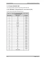
Table 5-2. Alarm Connector J6 Pin Assignment
Pin No.
Connection
1
Mod (Open Collector)
2
Mod (Normally Closed)
3
Demod (Open Collector)
4
Demod (Normally Closed)
5
Ground
6
Mod C
7
Mod (Normally Open)
8
Demod C
9
Demod (Normally Open)
Table 5-3. Alarm Indications
Alarm
Pin Description
None
6 – 7 shorted, 8 – 9 shorted
Mod
6 – 2 shorted, 5 – 1 driven high
Demod
8 – 4 shorted, 5 – 3 driven high
Summary of Contents for MM200
Page 2: ......
Page 14: ...Introduction MM200 High Speed Microwave Modem 1 2 TM086 Rev 4 1...
Page 18: ...Installation MM200 High Speed Microwave Modem 2 2 TM086 Rev 4 1...
Page 24: ...Theory of Operation MM200 High Speed Microwave Modem 3 6 TM086 Rev 4 1...
Page 76: ...User Interfaces MM200 High Speed Microwave Modem 4 52 TM086 Rev 4 1...
Page 93: ...MM200 High Speed Microwave Modem Electrical Interfaces TM086 Rev 4 1 5 17...
Page 96: ...Troubleshooting and Maintenance MM200 High Speed Microwave Modem 6 4 TM086 Rev 4 1...
Page 99: ...Technical Specifications MM200 High Speed Microwave Modem 7 2 TM086 Rev 4 1...
Page 100: ......
Page 147: ...MM200 High Speed Microwave Modem Appendix A TM086 Rev 4 1 A 47...
Page 148: ......
Page 186: ...Appendix B MM200 High Speed Microwave Modem B 38 TM086 Rev 4 1...
Page 192: ...Glossary MM200 High Speed Microwave Modem G 6 TM086 Rev 4 1...


