

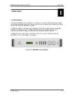


MM200 High-Speed Microwave Modem
Theory of Operation
TM086 - Rev. 4.1
3-5
This section is not yet complete.
3.3 Calculating 3dB Bandwidth of MM200 Modulated Carrier
1.
Find the combined interface data rate:
DR
C
= Interface 1 Data Rate + Interface 2 Data Rate + Interface 3 Data Rate + Interface 4
Data Rate
2.
Find the Total Data Rate plus R/S mux overhead, and guard band overhead:
DR
T
= DR
C
x (204/184) x 1.001
3.
Find Channel Baud Rate:
BR
C
= DR
T
/(QAM x N
C
)
Where N
C
= number of channels (one to four)
and QAM = 2 for 4 QAM
4 for 16 QAM
5 for 32 QAM
6 for 64 QAM
7 for 128 QAM
8 for 256 QAM
4.
Select Channel Spacing:
C
S
= from 1.1 to 1.5 times channel baud rate.
This number is usually 1.25 but may be set anywhere within the range of 1.1 to 1.5.
5.
Total 3 dB bandwidth = BR
C
x C
S
x (N
C
– 1) + BR
C
3.4 Input Level
Each IF channel has an independent dynamic range of 15 - 20 dB. This allows greater
performance during frequency selective fades. For normal operation, the MM200 was designed
to work with radios that have automatic gain control (AGC). The radio AGC will generally use the
average power of all the IF channels to set its power unlike the MM200 that independently AGCs
on each IF channel. When setting up the input level to the MM200, use the following procedure.
1.
If the Radio has a IF output level setting, adjust to the manufactures optimum point. If
there is none, set between 0 and –10 dBm.
2.
Verify that the input to the radio is not experiencing frequency selective fading or a deep
flat fade.
3.
Set the MM200 Demodulator attenuator (in the Demod menu) so that the AGC level
display reads approximately 340 (in the Monitor, Demodulator Menu). When multiple IF
channels exist there will be differences in AGC from channel to channel. These should
only be of concern if any channel exceeds 300 or is lower than 400. The AGC display
displays the value the M&C has assigned to the channel.
This display is un-calibrated and has a useful range of approximately 300 to 655. The number is
inversely proportional to the incoming signal (a higher number indicates a lower incoming signal).
Summary of Contents for MM200
Page 2: ......
Page 14: ...Introduction MM200 High Speed Microwave Modem 1 2 TM086 Rev 4 1...
Page 18: ...Installation MM200 High Speed Microwave Modem 2 2 TM086 Rev 4 1...
Page 24: ...Theory of Operation MM200 High Speed Microwave Modem 3 6 TM086 Rev 4 1...
Page 76: ...User Interfaces MM200 High Speed Microwave Modem 4 52 TM086 Rev 4 1...
Page 93: ...MM200 High Speed Microwave Modem Electrical Interfaces TM086 Rev 4 1 5 17...
Page 96: ...Troubleshooting and Maintenance MM200 High Speed Microwave Modem 6 4 TM086 Rev 4 1...
Page 99: ...Technical Specifications MM200 High Speed Microwave Modem 7 2 TM086 Rev 4 1...
Page 100: ......
Page 147: ...MM200 High Speed Microwave Modem Appendix A TM086 Rev 4 1 A 47...
Page 148: ......
Page 186: ...Appendix B MM200 High Speed Microwave Modem B 38 TM086 Rev 4 1...
Page 192: ...Glossary MM200 High Speed Microwave Modem G 6 TM086 Rev 4 1...


