4.2. Details
Antenna
The overview of different Jirous antenna types is listed in Section 3.6,
“Dimensions”. The antenna choice determines radio link properties.
The radio link calculation should be performed to determine proper
antenna size. Rough calculation can be done using a simple on-line
calculator.
•
see the Overview
•
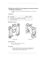
Antenna mounting kit
Other manufacturer's antennas can also be used with RAy2 links.
The RAy2 unit can be attached by means of special interconnetions.
There are several types of these parts for Andrew and Arkivator
antennas. It is also possible to develop interconnetions for other
antenna types.
•
see the Overview
•
The bracket for mounting FOD unit on the antenna.
Flexible waveguide mounting kit
The RAy2 unit can be attached to the antenna by flexible waveguide.
•
SET-RAY-FX-R100
•
SET-RAY-FX-R120
•
The bracket for mounting the flexible waveguide on the FOD
unit.
Cable bushing
•
SET-RAY2-CON-B
•
Basic set cable bushings and connectors
contains:
○ 3 pc standard PG21 bushing with nut
○ 2 pc blind plug Racom
○ 3 pc O-ring
○ 2 pc rubber sealing small diameter
○ 3 pc rubber sealing medium diameter
○ 2 pc rubber sealing big diameter
○ 1 pc DC connector
○ 1 pc tie wrap
○ 1 pc connector jumper
○ 1 pc RJ-45 ethernet connector
1
http://www.racom.eu/eng/products/microwave-link.html#calculation
2
http://www.racom.eu/eng/products/microwave-link.html#accessories
RAy2 Microwave Link – © RACOM s.r.o.
30
Accessories
Summary of Contents for Ray2
Page 2: ......
Page 6: ...6...
Page 64: ...7 3 Status Fig 7 6 Menu Status RAy2 Microwave Link RACOM s r o 64 Configuration...
Page 219: ...Appendix B Rain zone map 219 RACOM s r o RAy2 Microwave Link Rain zone map...
Page 234: ...234...


